Answered step by step
Verified Expert Solution
Question
1 Approved Answer
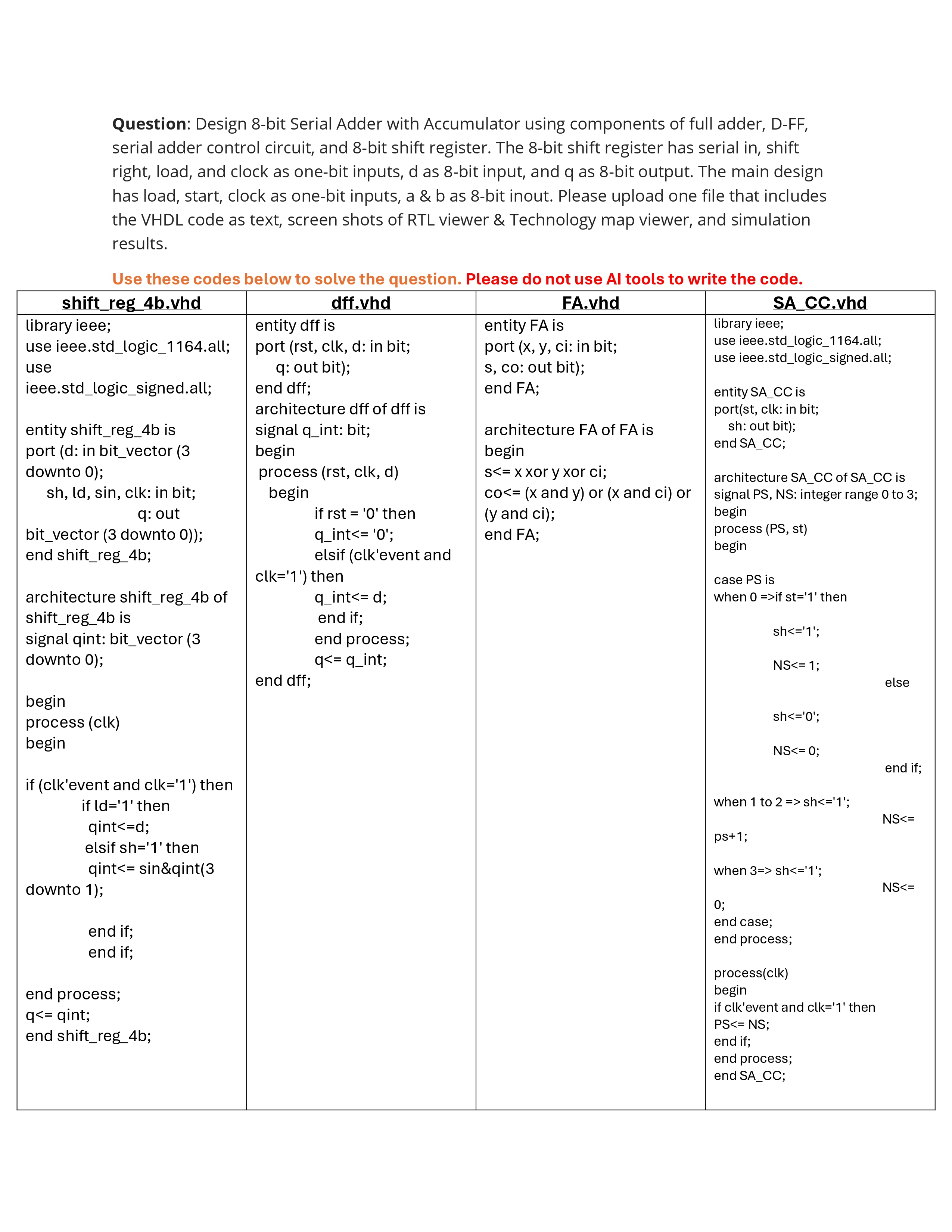
Question: Design 8 - bit Serial Adder with Accumulator using components of full adder, D - FF , serial adder control circuit, and 8 -
Question: Design bit Serial Adder with Accumulator using components of full adder, DFF serial adder control circuit, and bit shift register. The bit shift register has serial in shift right, load, and clock as onebit inputs, d as bit input, and q as bit output. The main design has load, start, clock as onebit inputs, a & b as bit inout.
Please upload the VHDL code as text,
screen shots of RTL viewer & Technology map viewer, and simulation results using quar tus Quartus Pri~me if you can.
Use these codes below to solve the question. Please do not use AI tools to write the code
shiftregbvhd:
library ieee;
use ieee.stdlogicall;
use ieee.stdlogicsigned.all;
entity shiftregb is
port d: in bitvector downto ;
sh ld sin clk: in bit;
q: out bitvector downto ;
end shiftregb;
architecture shiftregb of shiftregb is
signal qint: bitvector downto ;
begin
process clk
begin
if clkevent and clk then
if ld then
qintd;
elsif sh then
qint sin&qint downto ;
end if;
end if;
end process;
q qint;
end shiftregb;
dffvhd :
entity dff is
port rst clk d: in bit;
q: out bit;
end dff;
architecture dff of dff is
signal qint: bit;
begin
process rst clk d
begin
if rst then
qint;
elsif clkevent and clk then
qint d;
end if;
end process;
q qint;
end dff;
FAvhd :
entity FA is
port x y ci: in bit;
s co: out bit;
end FA;
architecture FA of FA is
begin
s x xor y xor ci;
cox and y or x and ci or y and ci;
end FA;
SACCvhd:
library ieee;
use ieee.stdlogicall;
use ieee.stdlogicsigned.all;
entity SACC is
portst clk: in bit;
sh: out bit;
end SACC;
architecture SACC of SACC is
signal PS NS: integer range to ;
begin
process PS st
begin
case PS is
when if st then
sh;
NS;
else
sh;
NS;
end if;
when to sh;
NS ps;
when sh;
NS;
end case;
end process;
processclk
begin
if clk'event and clk then
PS NS;
end if;
end process;
end SACC;

Step by Step Solution
There are 3 Steps involved in it
Step: 1

Get Instant Access to Expert-Tailored Solutions
See step-by-step solutions with expert insights and AI powered tools for academic success
Step: 2

Step: 3

Ace Your Homework with AI
Get the answers you need in no time with our AI-driven, step-by-step assistance
Get Started


