Question
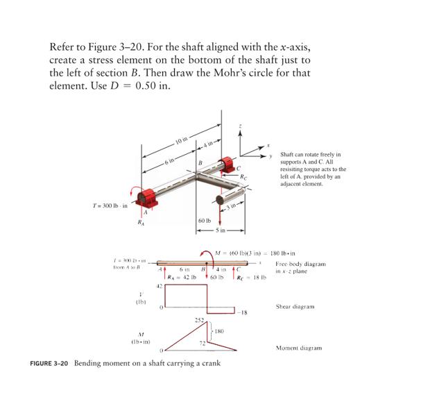
Refer to Figure 3-20. For the shaft aligned with the x-axis, create a stress element on the bottom of the shaft just to the

Refer to Figure 3-20. For the shaft aligned with the x-axis, create a stress element on the bottom of the shaft just to the left of section B. Then draw the Mohr's circle for that element. Use D = 0.50 in. T= 300 lb in 7 = 100D + 18 from A to V (16) M (lb-in) 42 6 in R 10 is 6 i 42 lb 4 in- # 60 lb B -5 in 4 in M-160 lb)(3 in) 180 lb in 60 lb 180 Re 0 FIGURE 3-20 Bending moment on a shaft carrying a crank 3 +C Re 18 lb -18 Shaft can rotate freely in supports A and C. All resisiting torque acts to the left of A provided by an adjacent element. Free body diagram. in x-2 plane Shear diagram Moment diagram
Step by Step Solution
3.50 Rating (160 Votes )
There are 3 Steps involved in it
Step: 1
to get First we will find Reaction forces on bearing A and an ide...
Get Instant Access to Expert-Tailored Solutions
See step-by-step solutions with expert insights and AI powered tools for academic success
Step: 2

Step: 3

Ace Your Homework with AI
Get the answers you need in no time with our AI-driven, step-by-step assistance
Get StartedRecommended Textbook for
Systems analysis and design
Authors: kenneth e. kendall, julie e. kendall
8th Edition
135094909, 013608916X, 9780135094907, 978-0136089162
Students also viewed these Accounting questions
Question
Answered: 1 week ago
Question
Answered: 1 week ago
Question
Answered: 1 week ago
Question
Answered: 1 week ago
Question
Answered: 1 week ago
Question
Answered: 1 week ago
Question
Answered: 1 week ago
Question
Answered: 1 week ago
Question
Answered: 1 week ago
Question
Answered: 1 week ago
Question
Answered: 1 week ago
Question
Answered: 1 week ago
Question
Answered: 1 week ago
Question
Answered: 1 week ago
Question
Answered: 1 week ago
Question
Answered: 1 week ago
Question
Answered: 1 week ago
Question
Answered: 1 week ago
Question
Answered: 1 week ago
Question
Answered: 1 week ago
Question
Answered: 1 week ago
View Answer in SolutionInn App


