?Reference?This is Part 6?https://www.chegg.com/homework-help/questions-and-answers/part-based-part-5-name-program-part6c-expand-functionality-simulator-part-5-allow-simulato-q29527064
This part is based on Part 6. Name this program as part7.c
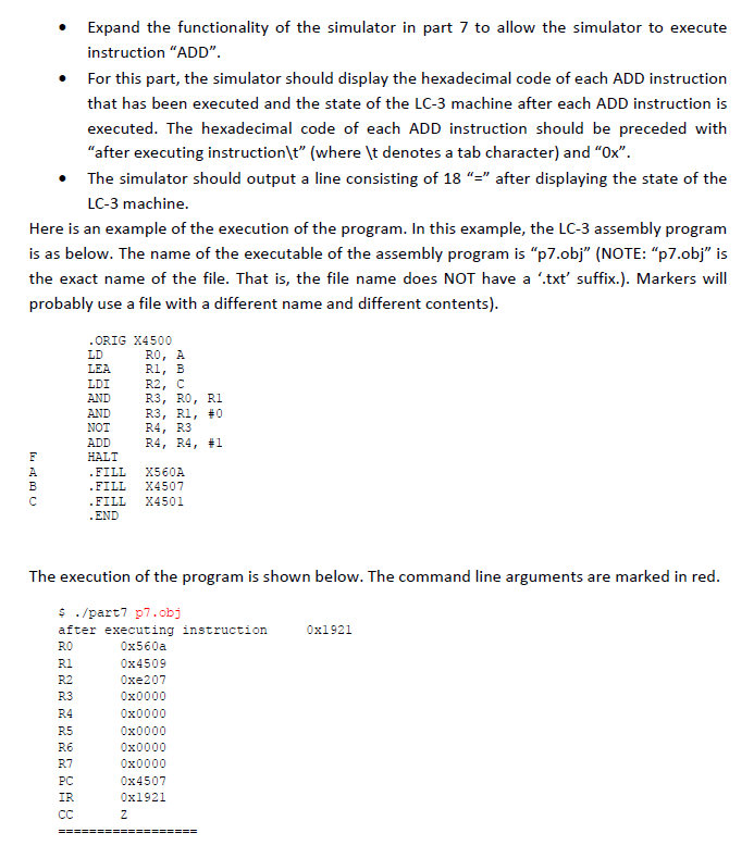
. Expand the functionality of the simulator in part 7 to allow the simulator to execute instruction "ADD" For this part, the simulator should display the hexadecimal code of each ADD instruction that has been executed and the state of the LC-3 machine after each ADD instruction is executed. The hexadecimal code of each ADD instruction should be preceded with . "after executing instructionlt" (where t denotes a tab character) and "Ox" . The simulator should output a line consisting of 18 "" after displaying the state of the LC-3 machine Here is an example of the execution of the program. In this example, the LC-3 assembly program is as below. The name of the executable of the assembly program is "p7.obj" (NOTE: "p7.obj" i:s the exact name of the file. That is, the file name does NOT have a '.txt' suffix.). Markers will probably use a file with a different name and different contents) .ORIG X4500 LDI AND AND NOT ADD HALT RO, A R1, B R2, C R3, RO, R1 R3, R1, #0 R4, R3 R4 , R4, #1 FILL X560A FILL X4507 FILL X4501 END The execution of the program is shown below. The command line arguments are marked in red s ./part7 p7.obj after executing instruction RO R1 R2 R.3 0x1921 0x560a 0x4509 0xe207 0x0000 0x0000 0x0000 0x0000 0x0000 0x4507 0x1921 R5 RE R7 PC IR . Expand the functionality of the simulator in part 7 to allow the simulator to execute instruction "ADD" For this part, the simulator should display the hexadecimal code of each ADD instruction that has been executed and the state of the LC-3 machine after each ADD instruction is executed. The hexadecimal code of each ADD instruction should be preceded with . "after executing instructionlt" (where t denotes a tab character) and "Ox" . The simulator should output a line consisting of 18 "" after displaying the state of the LC-3 machine Here is an example of the execution of the program. In this example, the LC-3 assembly program is as below. The name of the executable of the assembly program is "p7.obj" (NOTE: "p7.obj" i:s the exact name of the file. That is, the file name does NOT have a '.txt' suffix.). Markers will probably use a file with a different name and different contents) .ORIG X4500 LDI AND AND NOT ADD HALT RO, A R1, B R2, C R3, RO, R1 R3, R1, #0 R4, R3 R4 , R4, #1 FILL X560A FILL X4507 FILL X4501 END The execution of the program is shown below. The command line arguments are marked in red s ./part7 p7.obj after executing instruction RO R1 R2 R.3 0x1921 0x560a 0x4509 0xe207 0x0000 0x0000 0x0000 0x0000 0x0000 0x4507 0x1921 R5 RE R7 PC IR