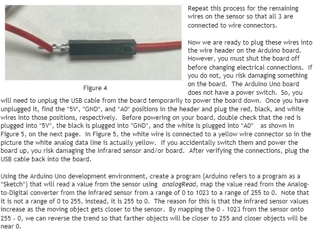
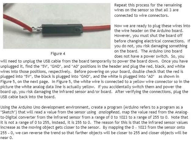
Repeat this process for the remaining wires on the sensor so that all 3 are connected to wire connectors. Now we are ready to plug these wires into the wire header on the Arduino board. However, you must shut the hoard off before changing electrical connections. If you do not, you risk damaging something on the board. The Arduino Uno board does not have a power switch. So, you will need to unplug the USB cable from the board temporarily to power the board down. Clnce you have unplugged it, find the "EM", "END", and "All" positions in the header and plug the red, blacl-t, and white wires into those positions, respectively. Before powering on your board, double check that the red is plugged into "5V", the black is plugged into "END", and the white is plugged into "AD" as shown in Figure 5, on the next page. In Figure 5, the white wire is connected to a yellow wire connector so in the picture the white analog data line is actually yellow. if you accidentally switch them and power the board up, you rislv: damaging the infrared sensor andfor board. After verifying the connections, plug the USB cable back into the board. Figure 4 Using the Arduino Uno development environment, create a program [Arduino refers to a program as a "Sltetch"]u that will read a value from the sensor using onclogReod, map the value read from the Malog- to-Digital converter from the infrared sensor from a range of [II to IDES to a range of 255 to II]. Note that it is not a range of D to 155, instead, it is 255 to G. The reason for this is that the infrared sensor values increase as the moving object gets closer to the sensor. By mapping the l] 1023 from the sensor onto 255 - 1}, we can reverse the trend so that farther objects will be closer to 255 and closer objects will be near l]