Answered step by step
Verified Expert Solution
Question
1 Approved Answer
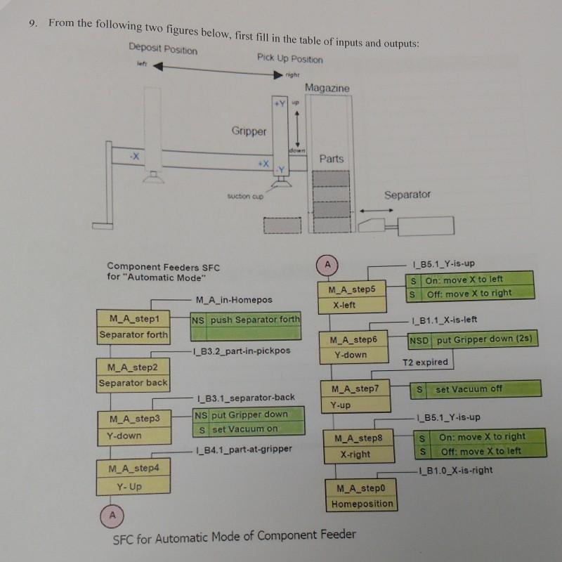
9. From the following two figures below, first fill in the table of inputs and outputs: Deposit Position Pick Up Position left right -X

9. From the following two figures below, first fill in the table of inputs and outputs: Deposit Position Pick Up Position left right -X Component Feeders SFC for "Automatic Mode" M_A_step1 Separator forth M_A_step2 Separator back M_A_step3 Y-down M_A_step4 Y- Up Gripper +X Suction cup down M_A_in-Homepos NS push Separator forth -I_B3.2_part-in-pickpos I_B3.1_separator-back NS put Gripper down S set Vacuum on I_B4.1_part-at-gripper Magazine Parts M_A_step5 X-left M_A_step6 Y-down M_A_step7 Y-up M_A_step8 X-right Separator M_A_step0 Homeposition SFC for Automatic Mode of Component Feeder I_B5.1_Y-is-up S S On: move X to left Off: move X to right I_B1.1 X-is-left NSD put Gripper down (25) T2 expired S set Vacuum off 1_B5.1_Y-is-up S S On: move X to right Off: move X to left -I_B1.0_X-is-right
Step by Step Solution
★★★★★
3.40 Rating (156 Votes )
There are 3 Steps involved in it
Step: 1
Fill in definition of Inputs Sensor X is right In Home position Part in pick position Separator back ...
Get Instant Access to Expert-Tailored Solutions
See step-by-step solutions with expert insights and AI powered tools for academic success
Step: 2

Step: 3

Document Format ( 2 attachments)
635db77d65bf7_178266.pdf
180 KBs PDF File
635db77d65bf7_178266.docx
120 KBs Word File
Ace Your Homework with AI
Get the answers you need in no time with our AI-driven, step-by-step assistance
Get Started


