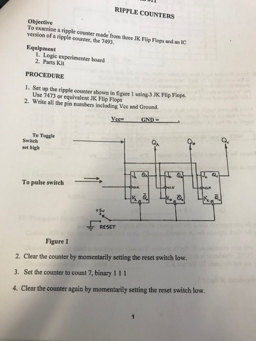
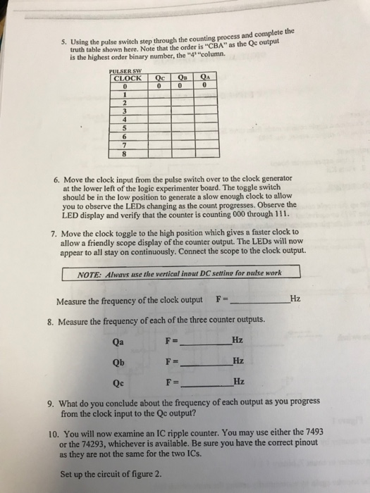
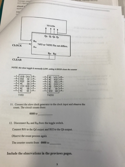
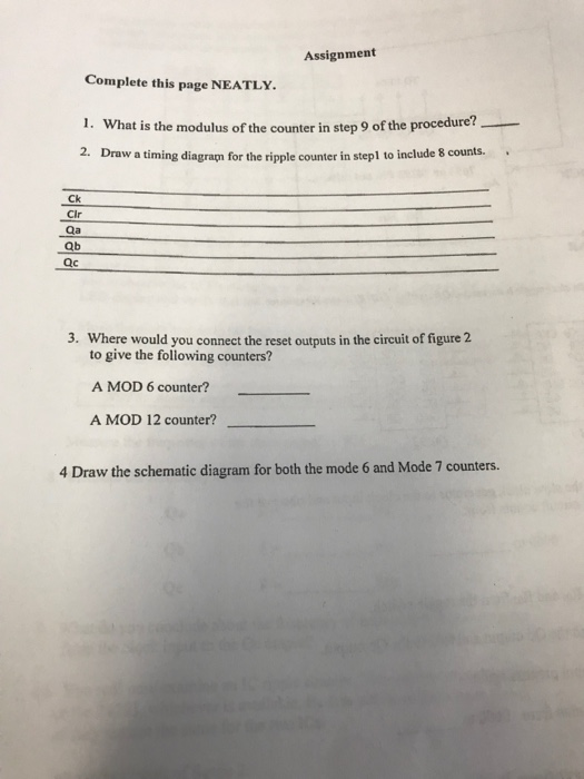
RIPPLE COUNTERS Objective To examine a ripple counter made from threeJK Flip Flops and an IC version of a ripple counter, the 7493. Equipment 1. Logic experimenter board 2. Parts Kit PROCEDURE 1. Set up the ripple counter shown in figure 1 using-3 JK Flip Flops 2. Write all the pin numbers including Vee and Ground. Use 7473 or equivalent JK Flip Flops To Toggle GA Switch set high ae To pulse switch RESET Figure I 2. Clear the counter by momentarily setting the reset switch low. 3. Set the counter to count 7, binary 111 4. Clear the counter again by momentarily setting the reset switch low. 5. Using the pulse switch step through the counting process and complete the truth table shown here. Note that the order is "CBA" as the Qc output is the highest order binary number, the "4 "column. ER 6. Move the clock input from the pulse switch over to the clock generator at the lower left of the logic experimenter board. The toggle switch should be in the low position to generate a slow enough clock to allow you to observe the LEDs changing as the count progresses. Observe the LED display and verify that the counter is counting 000 through 111 7. Move the clock toggle to the high position which gives a faster clock to allow a friendly scope display of the counter output. The LEDs will now appear to all stay on continuously. Connect the scope to the clock output NOTE: Ahwavs use the vertical inout DC setting for nulse work F- Hz Measure the frequency of the clock output 8. Measure the frequency of each of the three counter outputs Hz Hz Hz F- Qb F- Qc What do you conclude about the frequency of each output as you progress from the clock input to the Qc output? 9. 10. You will now examine an IC ripple counter. You may use either the 7493 or the 74293, whichever is available. Be sure you have the correct pinout as they are not the same for the two ICs. Set up the circuit of figure 2. and orga cloud TO LEDS 7493 or 74293 Pin out differs. CLOCK Roi Re CLEAR NOTE: the clear toggle is normally LOW, seming it HIGH clears the counter NC RO1 IR VCC GND 7493 74293 11. Connect the slow clock generator to the clock input and observe the count. The circuit counts from: 0000 to 12. Disconnect Ro1 and Ro from the toggle switch. Connect RO1 to the Qd output and R02 to the Qb output Observe the count process again The counter counts from 0000 to Include the observations in the previews pages. Assignment Complete this page NEATLY. I. What is the modulus of the counter in step 9 of the procedure 2. Draw a timing diagram for the ripple counter in stepl to include 8 counts.. Ck Cir Qb ac 3. Where would you connect the reset outputs in the circuit of figure 2 to give the following counters? A MOD 6 counter? A MOD 12 counter? 4 Draw the schematic diagram for both the mode 6 and Mode 7 counters