Answered step by step
Verified Expert Solution
Question
1 Approved Answer
SER232 Assignment 7 - [10 Points] Description This assignment covers the datapath components: Register File and ALU. You are supposed to create a custom


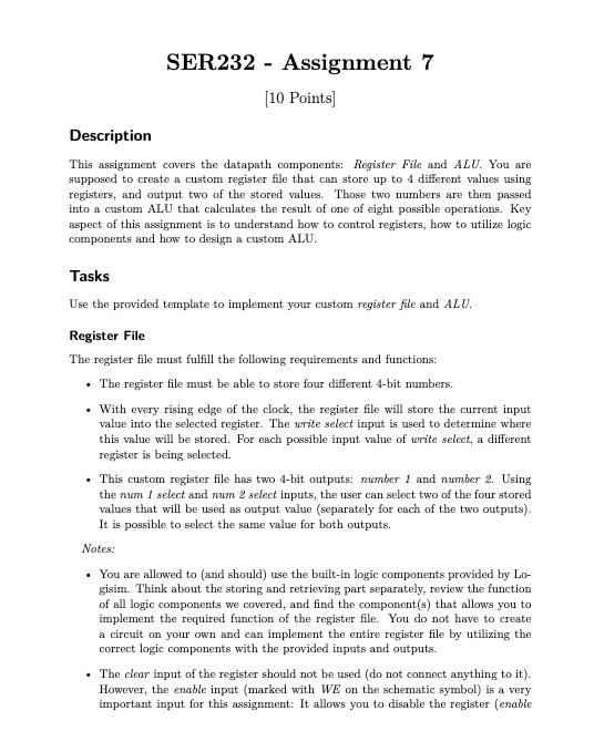
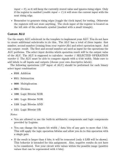
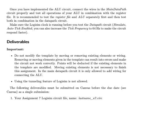
SER232 Assignment 7 - [10 Points] Description This assignment covers the datapath components: Register File and ALU. You are supposed to create a custom register file that can store up to 4 different values using registers, and output two of the stored values. Those two numbers are then passed into a custom ALU that calculates the result of one of eight possible operations. Key aspect of this assignment is to understand how to control registers, how to utilize logic components and how to design a custom ALU. Tasks Use the provided template to implement your custom register file and ALU. Register File The register file must fulfill the following requirements and functions: . The register file must be able to store four different 4-bit numbers. . With every rising edge of the clock, the register file will store the current input value into the selected register. The write select input is used to determine where this value will be stored. For each possible input value of write select, a different register is being selected. . This custom register file has two 4-bit outputs: number 1 and number 2. Using the num 1 select and num 2 select inputs, the user can select two of the four stored values that will be used as output value (separately for each of the two outputs). It is possible to select the same value for both outputs. Notes: . You are allowed to (and should) use the built-in logic components provided by Lo- gisim. Think about the storing and retrieving part separately, review the function of all logic components we covered, and find the component(s) that allows you to implement the required function of the register file. You do not have to create a circuit on your own and can implement the entire register file by utilizing the correct logic components with the provided inputs and outputs. . The clear input of the register should not be used (do not connect anything to it). However, the enable input (marked with WE on the schematic symbol) is a very important input for this assignment: It allows you to disable the register (enable input =0), so it will keep the currently stored value and ignores rising edges. Only if the register is enabled (enable input = 1) it will store the current input with the next rising edge. Remember to generate rising edges (toggle the clock input) for testing. Otherwise the registers will not store anything. The clock input of the register is located on the left side of the schematic symbol (marked with a small triangle). Custom ALU Use the empty ALU subcircuit in the template to implement your ALU. You do not have to create additional subcircuits to do this. The ALU has a total of three inputs: first number, second number (coming from your register file) and select operation input. And one output: result. The first and second number are used as input for the operations the ALU performs. The select input decides which operation result will be the output value of the ALU. The ALU is supposed to calculate: number 1 SELECTED OPERATION number 2. The ALU must be able to compute signals with a 4-bit width. Make sure to add labels to all inputs and outputs (choose your own descriptive labels). The following operations (OP input of ALU) should be performed for each binary select input combination: . 010: Addition .011: Subtraction 000: Multiplication 001: Division 100: Logic Bitwise XOR 101: Logic Bitwise NOR 110: Logic Bitwise AND 111: Logic Bitwise OR Notes: You are allowed to use the built-in arithmetic components and logic components provided by Logisim. You can change the inputs bit width / data bits of any gate to more that 1-bit. This will apply the logic operation bitwise and allow you do to this operation with a single gate. If the result is larger than 4 bits, it will be truncated (only 4 LSB will be shown). This behavior is intended for this assignment. Also, negative results do not have to be considered. Test your circuit with values within the possible range (positive values that can be represented with 4 bits). Once you have implemented the ALU circuit, connect the wires in the Main DataPath circuit properly and test all operations of your ALU in combination with the register file. It is recommended to test the register file and ALU separately first and then test both in combination in the datapath circuit. Make sure the Logisim clock is running before you test the Datapath circuit (Simulate, Auto-Tick Enabled; you can also increase the Tick Frequency to 64 Hz to make the circuit respond faster). Deliverables Important: Do not modify the template by moving or removing existing elements or wiring. Removing or moving elements given in the template can result into errors and make the circuit not work correctly. Points will be deducted if the existing elements in the template are modified. Moving existing elements is not necessary to finish this assignment. In the main datapath circuit it is only allowed to add wiring for connecting the ALU. Using the tunneling feature of Logisim is not allowed. The following deliverables must be submitted on Canvas before the due date (see Canvas) as a single submission: 1. Your Assignment 7 Logisim circuit file, name: lastname_a7.circ
Step by Step Solution
There are 3 Steps involved in it
Step: 1

Get Instant Access to Expert-Tailored Solutions
See step-by-step solutions with expert insights and AI powered tools for academic success
Step: 2

Step: 3

Ace Your Homework with AI
Get the answers you need in no time with our AI-driven, step-by-step assistance
Get Started


