Question
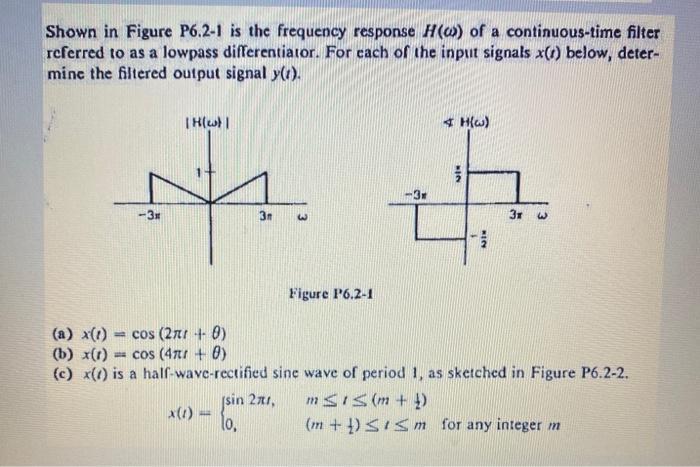
Shown in Figure P6.2-1 is the frequency response H(o) of a continuous-time filter referred to as a lowpass differentiator. For each of the input

Shown in Figure P6.2-1 is the frequency response H(o) of a continuous-time filter referred to as a lowpass differentiator. For each of the input signals x(r) below, deter- mine the filtered output signal y(t). -3 |H(w) | 3n x(1) = jsin 2x1, 10, Figure P6.2-1 3r * H(w) FIN MICH 3x (a) x(1)
Step by Step Solution
3.38 Rating (148 Votes )
There are 3 Steps involved in it
Step: 1

Get Instant Access to Expert-Tailored Solutions
See step-by-step solutions with expert insights and AI powered tools for academic success
Step: 2

Step: 3

Ace Your Homework with AI
Get the answers you need in no time with our AI-driven, step-by-step assistance
Get StartedRecommended Textbook for
Principles of Communications Systems, Modulation and Noise
Authors: Rodger E. Ziemer, William H. Tranter
7th edition
978-1-118-0789, 1118078918, 978-8126556793
Students also viewed these Programming questions
Question
Answered: 1 week ago
Question
Answered: 1 week ago
Question
Answered: 1 week ago
Question
Answered: 1 week ago
Question
Answered: 1 week ago
Question
Answered: 1 week ago
Question
Answered: 1 week ago
Question
Answered: 1 week ago
Question
Answered: 1 week ago
Question
Answered: 1 week ago
Question
Answered: 1 week ago
Question
Answered: 1 week ago
Question
Answered: 1 week ago
Question
Answered: 1 week ago
Question
Answered: 1 week ago
Question
Answered: 1 week ago
Question
Answered: 1 week ago
Question
Answered: 1 week ago
Question
Answered: 1 week ago
Question
Answered: 1 week ago
Question
Answered: 1 week ago
Question
Answered: 1 week ago
Question
Answered: 1 week ago
Question
Answered: 1 week ago
View Answer in SolutionInn App


