Answered step by step
Verified Expert Solution
Question
1 Approved Answer
Sketch diagrams showing the relationship between Reynolds number, Re, and friction factor, Cf for the head lost when oil flows through pipes of varying

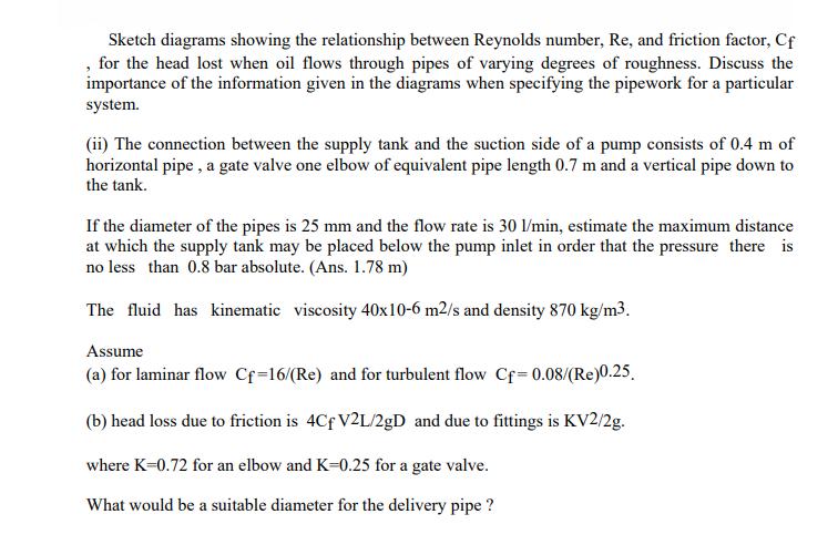
Sketch diagrams showing the relationship between Reynolds number, Re, and friction factor, Cf for the head lost when oil flows through pipes of varying degrees of roughness. Discuss the importance of the information given in the diagrams when specifying the pipework for a particular system. (ii) The connection between the supply tank and the suction side of a pump consists of 0.4 m of horizontal pipe, a gate valve one elbow of equivalent pipe length 0.7 m and a vertical pipe down to the tank. If the diameter of the pipes is 25 mm and the flow rate is 30 l/min, estimate the maximum distance at which the supply tank may be placed below the pump inlet in order that the pressure there is no less than 0.8 bar absolute. (Ans. 1.78 m) The fluid has kinematic viscosity 40x10-6 m2/s and density 870 kg/m3. Assume (a) for laminar flow Cf=16/(Re) and for turbulent flow Cf=0.08/(Re)0.25. (b) head loss due to friction is 4Cf V2L/2gD and due to fittings is KV2/2g. where K=0.72 for an elbow and K-0.25 for a gate valve. What would be a suitable diameter for the delivery pipe ?
Step by Step Solution
★★★★★
3.35 Rating (155 Votes )
There are 3 Steps involved in it
Step: 1
The detailed ...
Get Instant Access to Expert-Tailored Solutions
See step-by-step solutions with expert insights and AI powered tools for academic success
Step: 2

Step: 3

Ace Your Homework with AI
Get the answers you need in no time with our AI-driven, step-by-step assistance
Get Started


