Answered step by step
Verified Expert Solution
Question
1 Approved Answer
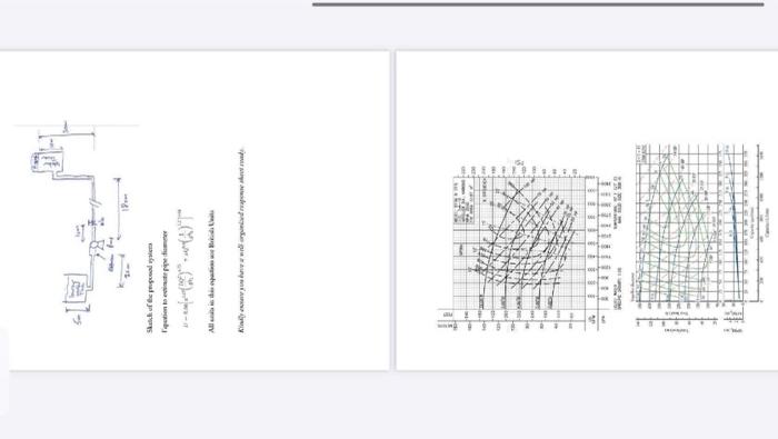
Sketch of the proposed system F.quation to estimate pipe diameter [ i=0.66left[e^{1.25}left(rac{L Q^{2}}{g / H_{2}} ight)^{4.75}+ u Q^{2.4}left(rac{L}{g H_{L}} ight)^{3,2} ight]^{0.04} ] All units in
Sketch of the proposed system F.quation to estimate pipe diameter [ i=0.66left[e^{1.25}left(rac{L Q^{2}}{g / H_{2}} ight)^{4.75}+ u Q^{2.4}left(rac{L}{g H_{L}} ight)^{3,2} ight]^{0.04} ] All units in this equation are British Units Kindly ensire you have a well-orgamized response sheet ready.
Design a pumping system for a municipal water supply application where water needs to be lifted from a lower vented underground reservoir (5m above the pump) to a pressurized water tower situated 30 meters above the pump. The flow rate required is 1500liter/minute. Assume the physical properties of the wastewater are same as that of water at 15C. The pressure at the top of the water tower is 20kpag. The horizontal distance between the pump and the water tower is 180 meters. The vertical pipe from the pump to entrance of the water tower tank is 20m. A sketch is shown below.
The system includes pipes with varying diameters and fittings. The pipe from the reservoir to the pump station is X inches in diameter schedule 40 and 20m length, followed by a sudden expansion to (X+1) inches in diameter new schedule 40 at the pump suction. At the exit of the pump, the pipe diameter is X inches for the horizontal and vertical section leading to the water tower. Additionally, there two 90-degree standard elbows and one fully open globe valve located at 10 m from the exit of pump.
You can use the equation below to estimate the pipe diameter, X, with a maximum allowable head load, hl as 22ft/100ft pipe length.
1. Based on the requirements of the system, choose the right pump type. The suction pipe diameter is same as pipe size find from the equation below.
2. Compute the overall head losses considering friction losses in the fittings, pipes, and elevation variations
3. To avoid cavitation, find the Net Positive Suction Head Required (NPSHR) for the selected pump. and make sure it falls within the permitted NPSHA. Give thorough NPSHR and head loss computations.
Compute a resistance curve for the system across the entire pump capacity. Display all of the points you used for the plotting in a table.
5. Draw the resistance curve
6. What are the pump characteristics (efficiency, horsepower, NPSHr) if pump impeller casting is 7 inches
7. What adjustments could you recommend lowering the amount of power needed, and why? : Could you provide calculations

qution to ente AT Kindly save you have a well organized and
Step by Step Solution
There are 3 Steps involved in it
Step: 1

Get Instant Access to Expert-Tailored Solutions
See step-by-step solutions with expert insights and AI powered tools for academic success
Step: 2

Step: 3

Ace Your Homework with AI
Get the answers you need in no time with our AI-driven, step-by-step assistance
Get Started


