Standard Lab Setup The standard lab setup will consist of two routers, one switch, one server, and two PCs. Each of these devices will be pre-configured with such information as device names, IP addresses, gateways, and connections. 

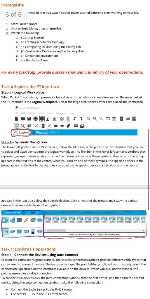
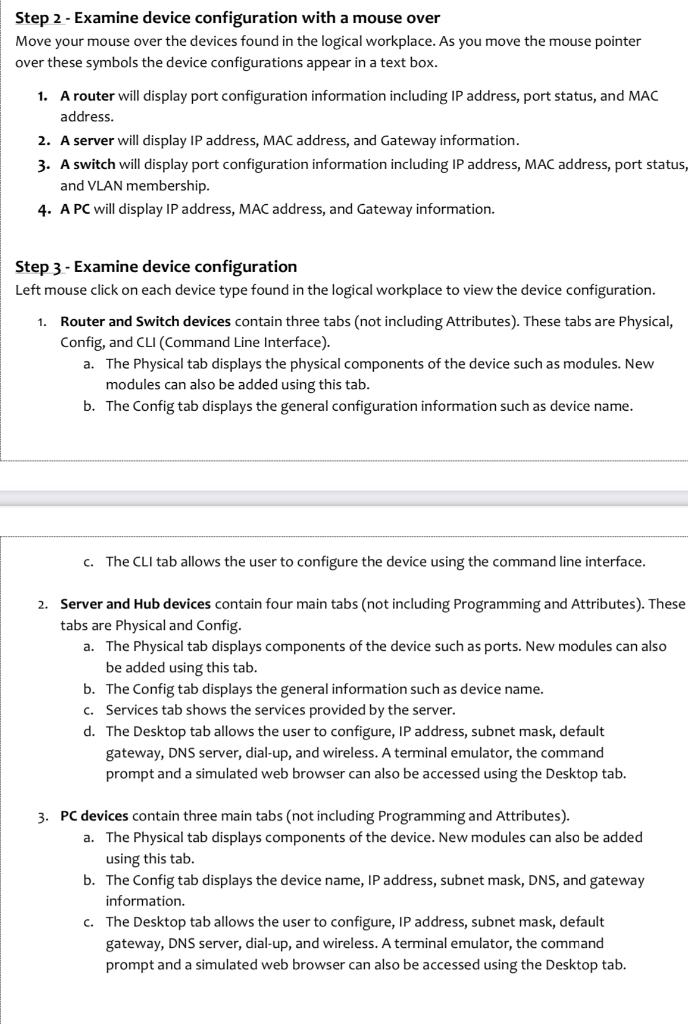
Prerequisite 3 of 5 mended that you watch packet tracer tutorial before to start working on your lab. 1. Start Packet Tracer 2. Click on help Menu, then on tutorials 3. Watch the following: a. 1 Getting Started b. 2-1 Creating a network topology c. 31 Configuring Devices using the Config Tab d. 3-2 Configuring Devices using the Desktop Tab e. 4-1 Simulation Environment f. 4-2 Simulation Panel For every task/step, provide a screen shot and a summary of your observations. Task 1: Explore the PT interface Step 1 - Logical Workplace When Packet Tracer starts, it presents a logical view of the network in real-time mode. The main part of the PT interface is the Logical Workplace. This is the large area where devices are placed and connected. Cisco Packet Tracer le Options View Tools Extensions QQQ Qx Logical Physical 304, y 2 Step 2 - Symbols Navigation The lower left portion of the PT interface, below the blue bar, is the portion of the interface that you use to select and place devices into the logical workplace. The first box in the lower left contains symbols that represent groups of devices. As you move the mouse pointer over these symbols, the name of the group appears in the text box in the center. When you click on one of these symbols, the specific devices in the group appear in the box to the right. As you point to the specific devices, a description of the device appears in the text box below the specific devices. Click on each of the groups and study the various devices that are available and their symbols. T 00 05:00 31 4320 121 290 291 X BERGW829 1240 (Select a Device to Drag and Drop to the Workspace) Task 2: Explore PT operations Step 1 - Connect the devices using auto connect Click on the connections group symbol. The specific connection symbols provide different cable types that can be used to connect devices. The first specific type, the gold lightning bolt, will automatically select the connection type based on the interfaces available on the devices. When you click on this symbol, the pointer resembles a cable connector. To connect two devices click the auto connection symbol, click the first device, and then click the second device. Using the auto connection symbol, make the following connection: Connect the Eagle Server to the R1-ISP router. Connect PC-PT 1A to the S1-Central switch. Step 2 - Examine device configuration with a mouse over Move your mouse over the devices found in the logical workplace. As you move the mouse pointer over these symbols the device configurations appear in a text box. 1. A router will display port configuration information including IP address, port status, and MAC address. 2. A server will display IP address, MAC address, and Gateway information. 3. A switch will display port configuration information including IP address, MAC address, port status, and VLAN membership. 4. A PC will display IP address, MAC address, and Gateway information. Step 3 - Examine device configuration Left mouse click on each device type found in the logical workplace to view the device configuration. 1. Router and Switch devices contain three tabs (not including Attributes). These tabs are Physical, Config, and CLI (Command Line Interface). a. The Physical tab displays the physical components of the device such as modules. New modules can also be added using this tab. b. The Config tab displays the general configuration information such as device name. C. The CLI tab allows the user to configure the device using the command line interface. 2. Server and Hub devices contain four main tabs (not including Programming and Attributes). These tabs are Physical and Config. a. The Physical tab displays components of the device such as ports. New modules can also be added using this tab. b. The Config tab displays the general information such as device name. C. Services tab shows the services provided by the server. d. The Desktop tab allows the user to configure, IP address, subnet mask, default gateway, DNS server, dial-up, and wireless. A terminal emulator, the command prompt and a simulated web browser can also be accessed using the Desktop tab. 3. PC devices contain three main tabs (not including Programming and Attributes). a. The Physical tab displays components of the device. New modules can also be added using this tab. b. The Config tab displays the device name, IP address, subnet mask, DNS, and gateway information. c. The Desktop tab allows the user to configure, IP address, subnet mask, default gateway, DNS server, dial-up, and wireless. A terminal emulator, the command prompt and a simulated web browser can also be accessed using the Desktop tab


