Question: Summarize this for me Someone who understand MEA and HEA very well. And please make sure the summary is 2 pages . no less than

Summarize this for me Someone who understand MEA and HEA very well. And please make sure the summary is 2 pages . no less than 2 pages plz thanks
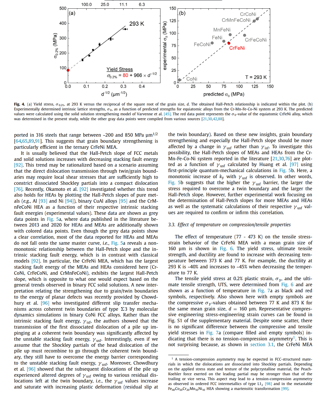
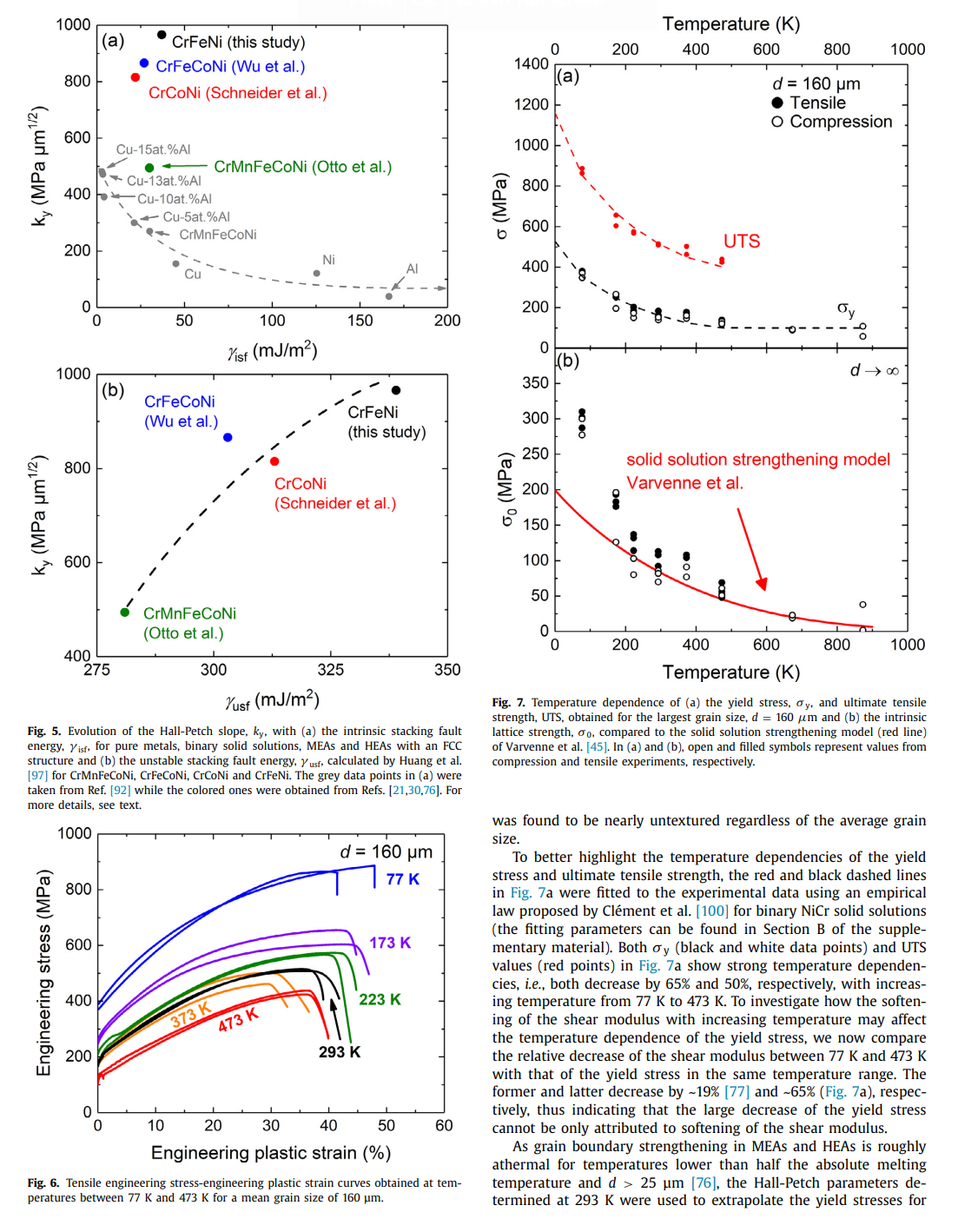
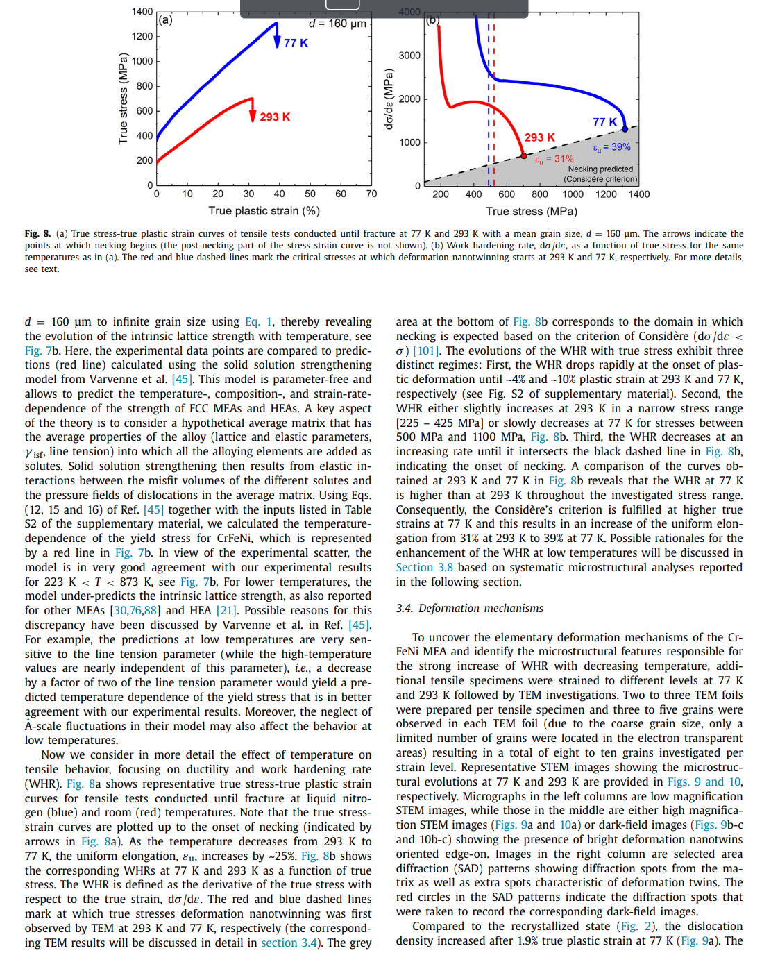
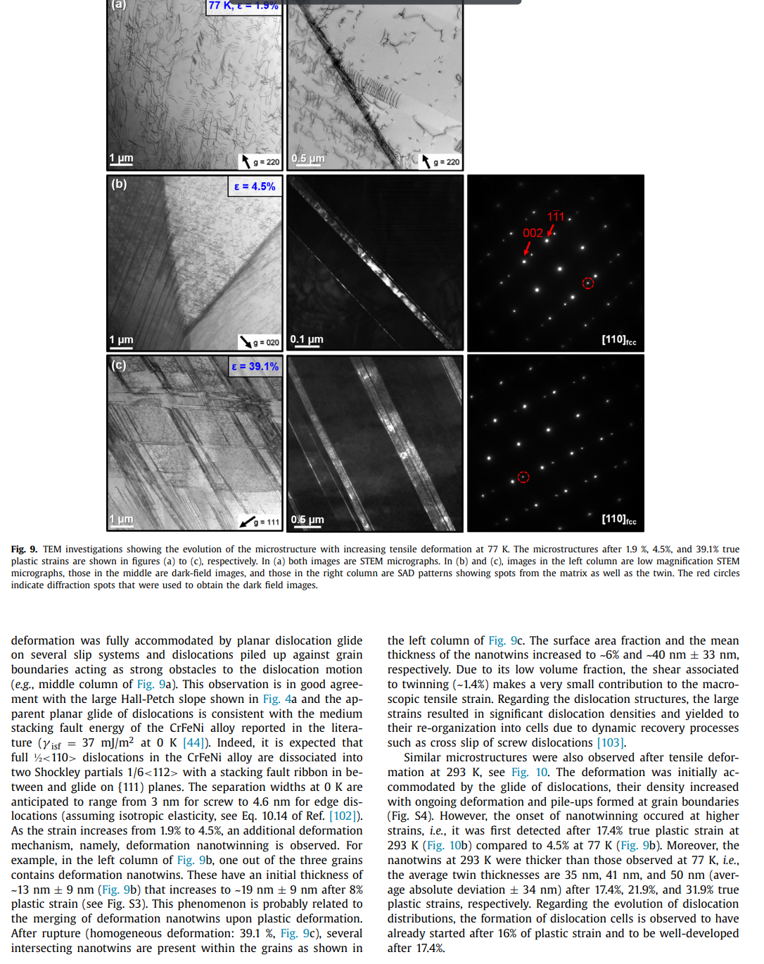
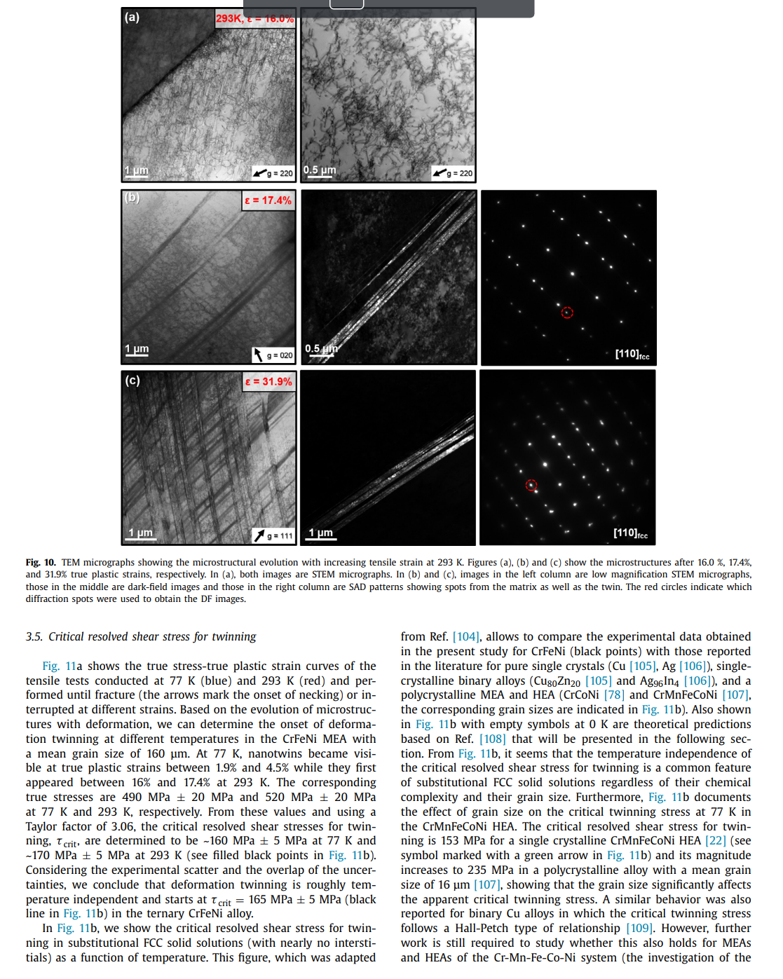
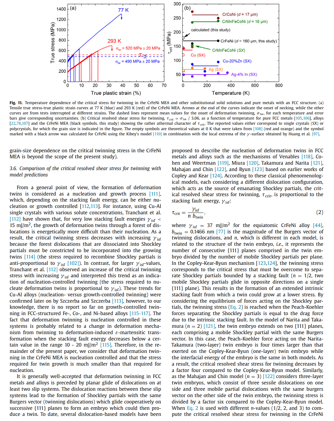
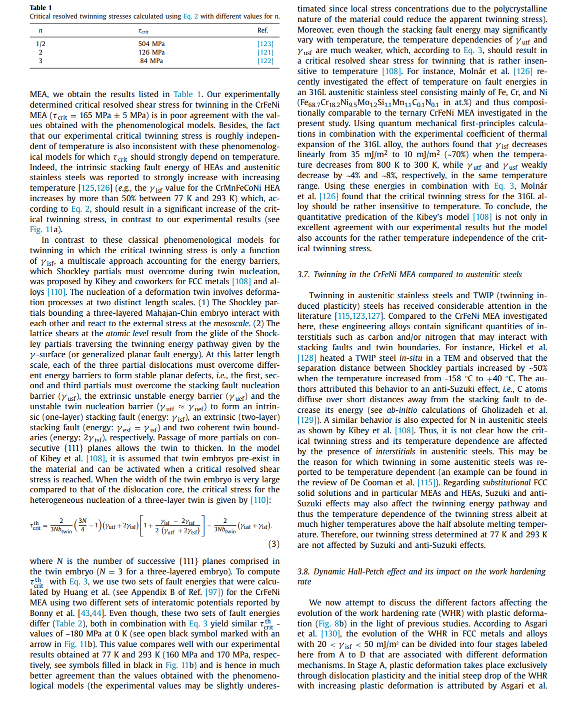
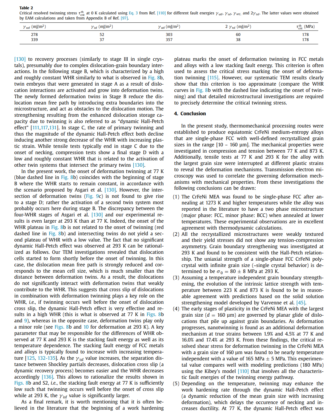
Effects of temperature on mechanical properties and deformation mechanisms of the equiatomic CrFeNi medium-entropy alloy Mike Schneider*, Guillaume Laplanche Institute for Materials, Ruhr-University Bochum, Universittsstr. 150, 44801 Bochum, Germany A R T I C L E I N FO A B S T R A C T Article history: An equiatomic CrFeNi medium-entropy alloy (MEA) that constitutes a cornerstone of austenitic stain- Received 11 July 2020 less steels and Fe-based superalloys is investigated. Anneals at various temperatures revealed that CrFeNi Revised 12 October 2020 forms a stable face-centered cubic (FCC) solid solution above 1223K. Based on this result, this alloy Accepted 3 November 2020 Available online 19 November 2020 was cold-worked and recrystallized between 1273K and 1473K to produce different grain sizes. Compression tests were carried out at 293K to investigate grain boundary strengthening (Hall-Petch slope: FeCrNi sic uniaxial lattice strength (80 MPa). Additional compression and tensile tests were performed between Medium-entropy and high-entropy alloys 77K and 873K to study the effect of temperature on mechanical properties and deformation mechaDeformation twinning nisms. Ductility, yield and ultimate tensile strengths increased with decreasing temperature. To reveal Critical twinning stress Austenitic stainless steels the active deformation mechanisms in CrFeNi with the coarsest grain size (160 m ), tensile tests at 77K and 293K were interrupted at different strains followed by transmission electron microscopy analyses. In all cases, the deformation was accommodated by dislocation glide at low strains, while twinning additionally occurred above a critical resolved shear stress of 165MPa, which was roughly temperature independent. This value compares well with predictions (180 MPa) based on the Kibey's model for twin nucleation. Moreover, the fact that this value is roughly temperature-independent is also consistent with the Kibey's model since the twin nucleation barrier (unstable twin stacking fault energy) of FCC metals and alloys does not vary significantly with temperature. ( 2020 The Authors. Published by Elsevier Ltd on behalf of Acta Materialia Inc. This is an open access article under the CC BY license (http://creativecommons.org/licenses/by/4.0/) 1. Introduction solutions were reported to exhibit an attractive combination of mechanical properties, namely, high work-hardening rate [21,28], Conventional alloys classically consist of a base element, e.g., Fe good ductility and ultimate tensile strength [29-37], high resistance in steels, to which small amounts of alloying elements such as C to fatigue-crack growth [38,39], and exceptional fracture toughness and Cr are added to improve strength and corrosion resistance, [40,41] (e.g., >200MPam1/2 for CrCoNi and CrMnFeCoNi). respectively. In contrast, medium- and high-entropy alloys (MEAs Wu et al. [42] were the first to investigate binary, ternary, and and HEAs) break down the conventional notions of solutes and quaternary equiatomic subsystems of the Cantor alloy with a fosolvents. While HEAs have been defined as alloys containing five cus on phase stability after casting and thermomechanical processor more elements, MEAs comprise two to four principal elements ing. While most of these alloys remained single-phase FCC after in near-equiatomic proportions [1,2]. Most studies in this research cold rolling followed by recrystallization, the ternary CrFeNi MEA, field have been so far focused on fundamental aspects of single- which was initially single-phase FCC after casting, was found to be phase concentrated solid solutions such as their phase stability two-phase FCC + BCC (body-centered cubic) after thermomechan[3-9], diffusion behavior [10-14], elastic properties [15-19], me- ical processing. Therefore, the first objective of the present paper chanical properties and deformation mechanisms [20-26]. To date, is to experimentally determine the solvus temperature of the BCC one of the most thoroughly investigated material systems in- phase and to establish a processing route to produce single-phase cludes the face-centered cubic (FCC) CrMnFeCoNi HEA, also known FCC CrFeNi alloys with well-defined recrystallized grain sizes. as Cantor alloy [27] and its equiatomic subsystems. These solid To date, little is known regarding the intrinsic physical and mechanical properties of the CrFeNi MEA. For instance, Bonny et al. [43,44] have developed an embedded atom method (EAM) * Corresponding author: type interatomic potential for the ternary CrFeNi system to E-mail address: mike.schneiderirub.de (M. Schneider). investigate the deformation mechanisms responsible for the degra- microscopy (TEM) and presented in Section 3.4. From these obdation of austenitic stainless steels submitted to harsh service en- servations, the critical stress needed to trigger deformation twinvironments (e.g., high mechanical and thermal stresses). Using this ning is deduced in Section 3.5 and compared to theoretical predicpotential, the authors predicted the composition-dependent stack- tions in Section 3.6. From a more general viewpoint, we discuss in ing fault energy (iff) for the entire ternary CrFeNi system, in- Section 3.7 how deformation twinning in the CrFeNi MEA may difcluding that of the equiatomic CrFeNi alloy (0mJ/m2[44]). In- fer from that reported in austenitic stainless. In Section 3.8 , we disterestingly, one of the most successful theories describing solid so- cuss under which conditions deformation twinning promotes the lution strengthening in FCC HEAs [45,46] was originally tested and work hardening rate. Finally, Section 4 briefly sums up the main validated based on molecular static simulations performed for a set findings of the present article. of CrFeNi alloys using the interatomic potentials of Bonny et al. [43,44]. Indeed Varvenne et al. [45] investigated the effect of al2. Experimental details loy composition in CrxFe(1x/2)Ni(1x/2) alloys (for x=10,20,33, 40 and 50 at.\%) on shear modulus, isf activation parameters, and 2.1. Materials preparation the intrinsic lattice strength at 0K[45]. However, the experimental validation of these simulations is still missing. Therefore, the An equiatomic Cr33.3Fe33.3Ni33.3 (composition in at.\%) alloy second objective of the present study is to clarify whether the in- weighing 2.1kg was produced using a vacuum induction melting trinsic lattice strength of the equiatomic CrFeNi alloy as well as furnace of type Leybold Heraeus IS 1/ III operating in the range [5 its temperature dependence support the simulations of Varvenne 20kW. For this purpose, raw elements having purities 99.9 et al. [45] and their theory of solid solution strengthening in FCC wt.\% were used. To prevent oxidation and evaporation of the eleHEAs and MEAs. ments during casting, the chamber of the furnace was evacuated Alloys comprising high concentrations of Cr, Fe, and Ni have to 3 mbar and subsequently filled with Ar (purity: 99.998 vol.\%) to been used as engineering materials for more than one century [47]. a pressure of 500 mbar. After all elements were fully melted, the Modern austenitic stainless steels and Fe-based superalloys contain melt was poured into a cylindrical steel mold (45 mm diameter, large quantities of Cr and Ni to enhance solid solution strength- 160mm height) where it solidified and was cooled to room temening, corrosion resistance (Cr) and stabilize the FCC matrix (Ni). perature (RT). The cast ingot was then turned on a lathe resulting Austenitic stainless steels are commonly used as in-core compo- in a diameter of 40mm and it was cut perpendicular to the rod nents for nuclear light water reactors [48] and Fe-base superal- axis into two halves ( 80mm height each). Those two pieces were loys are employed as turbine disks [49] and in gas compressors sealed individually in evacuated quartz tubes (3105 mbar) and [50]. Both these engineering alloys have received considerable in- homogenized at 1473K for 48h. Afterward, the homogenized interest from experimental [51-58] and theoretical [59-63] points of gots were removed from their quartz tubes and cold-worked at RT view within the past 20 years. Given its compositional similari- using a four-die rotary swaging machine of type HMP R6-4-120ties, the equiatomic, single-phase FCC Cr33.3Fe33.3Ni33.3 (composi- 21S (HMP Umformtechnik GmbH, Pforzheim, Germany). The diamtion in at.\%) MEA constitutes a cornerstone of these engineering eter of both ingots was reduced from 40mm to 16.5mm (true alloys and a better understanding of its phase stability, mechanical strain 1.8 ) in seven steps resulting in two 250 -mm long rods. properties, and deformation behavior may help to further optimize For more details regarding the swaging procedure, the reader may these classes of materials [49,50,6466]. In the case of polycrys- refer to Ref. [73]. talline Fe-based superalloys, their macroscopic yield stress mainly From the first rod, cylindrical compression specimens (4 mm diconsists of three contributions: (i) solid solution strengthening, (ii) ameter, 8mm height) and flat dog-bone shaped tensile specimens grain size strengthening, and (iii) particle strengthening due to co- with a gauge length of 20mm (width: 4mm, thickness: 1.2mm ) herent and ordered nano-precipitates of type L12[67]. The lat- were manufactured by electrical discharge machining with their ter contribution is known to nearly double the yield strength of the loading axes parallel to the axis of the swaged rod. The specimaterial compared to that of solutionized superalloys (single-phase mens were sealed in evacuated quartz tubes and heat-treated at FCC) [68,69]. However, as it is very complex to separate these three 1473K for 60min resulting in an average grain size of 160m strengthening mechanisms in multi-phase alloys, the relative con- (see Table 1 of the corresponding "Data in Brief" article [74]). To tributions of the two former ones could be better investigated us- produce other recrystallized microstructures with finer grain sizes, ing the single-phase FCC CrFeNi MEA. This constitutes the third the second swaged rod with an initial diameter of 16.5 mm was scientific objective of the present work. recrystallized for 1h at 1273K in air resulting in a grain size Recent attempts were made by Zhang et al. [66] to improve the of 34m and its diameter was reduced by swaging at RT from strength of Fe-base superalloys by combining strengthening from 16.5mm to 8.1mm (true strain 1.4 ). From this thinner rod, addeformation nano-twins and -nanoprecipitates. For this reason ditional compression specimens with their compression axes paraland the fact that other FCC HEAs and MEAs [70-72] also deform lel to the rod axis were fabricated by turning them on a lathe. The through deformation twinning in addition to conventional disloca- faces of all compression specimens were ground using a corundum tion plasticity, the fourth objective of the present study is to in- grinding stone (particle size 250m ) at a speed of 1400rpm vestigate whether deformation twinning occurs in the equiatomic to achieve a parallelism better than 1. All compression specimens CrFeNi alloy and, if applicable, to characterize the critical stress at were sealed in evacuated quartz tubes along with metallographic which twinning is triggered. specimens, which were cut parallel to the deformation axis of the The remainder of the present study is organized as follows. recrystallized rods for texture and grain size analyses. The samples In addition to experimental methods (e.g., sample preparation, were then annealed between 1273K and 1473K for times in the electron microscopy, and mechanical testing). Section 2 describes range [15 - 60min ). This resulted in six different grain sizes (the the thermomechanical treatments employed to obtain the single- corresponding grain size distributions can be found in Table 1 of phase FCC CrFeNi MEA with different grain sizes. In Section 3.1, Ref. [74]). we present the experimental results regarding phase stability, microstructure, and texture. In Sections 3.2 and 3.3, we show the effect of grain size and temperature on the mechanical properties of the ternary CrFeNi MEA, respectively. The microstructural evolution For phase, texture, and grain size analyses, the recrystallized during tensile straining is investigated by transmission electron metallographic specimens were ground in a first step with SiC abrasive papers down to a grit size of 8m. In a second step. sion punches, as well as the faces of the compression specimens, the samples were polished with diamond suspensions to 1m. were lubricated with a MoS 2 grease to limit friction during testThe last polishing step was performed in a vibropolishing ma- ing. Prior to uniaxial tests at 77K, specimens, as well as compreschine (Buehler Vibromet 2) using colloidal silica (particle size of sion punches or tensile grips, were immersed in liquid nitrogen for 0.06m ) and a polishing time of two days. Phase characterization 30min and kept immersed during testing. Uniaxial tests between was performed using X-ray diffraction in a PANalytical X'pert Pro 173K and 873K were performed in air in a temperature-controlled MRD diffractometer equipped with a 4-bounce germanium (220) chamber, in which the specimens were held at these temperatures monochromator having a Cu-K radiation of 0.154nm. The XRD for 45min before testing. Tests performed at RT and 77K were characterization was carried out in a 2 range between 20 and conducted using an Epsilon Technology Corp. axial extensometer, 120 using a step size of 0.006. Texture was determined by elec- which was directly attached to the gauge section. Since this extron backscatter diffraction (EBSD) using an accelerating voltage of tensometer could not be used at the other testing temperatures, 30kV, a working distance of 11-15 mm, and step sizes ranging strains were estimated indirectly from the crosshead displacement from 0.25m to 4m depending on the average grain size. All using the following procedure. The tensile data obtained at 77K these EBSD measurements were performed in a scanning electron and 293K were analyzed using both the strains determined with microscope (SEM) of type Quanta FEI 650 ESEM equipped with a the extensometer and those determined from the crosshead disHikari XP camera (EDAX, AMETEK). Indexing of the Kikuchi pat- placement. This allowed estimating a correction factor that acterns was performed using the TSL OIM Analysis software (version counts for the deformation in the shoulders of the tensile speci6.2.0). In the present work, texture is represented by inverse pole men and the deformation of the load-train. figures (IPFs) corresponding to the rod axis (parallel to the loading axis) because no texture could be detected for directions normal 3. Results and discussion to the swaging direction. Calculations of the IPFs were carried out using the harmonic expansion method up to a series expansion de- 3.1. Phase stability, microstructure, and texture gree of 22 and a Gaussian half-width of 5. Four backscatter electron (BSE) micrographs, taken at locations Two representative XRD patterns of cold-worked rods after spaced several millimeters apart between the center and the outer 1-h anneals at 1473K and 1273K are presented in Figs. 1a and surface of the recrystallized rods were used for grain size analyses. b, respectively. As no diffraction peaks were detected between 20 The average grain size was determined with the Heyn linear inter- and 40, this angular range is omitted in Fig. 1. The XRD patterns cept method using eight lines of identical length per micrograph. show only diffraction peaks belonging to an FCC phase with a latFollowing the procedure outlined in ASTM E-112 [75], each line in- tice parameter of 0.3591nm. The corresponding BSE micrographs tersected at least 50 grains, resulting in 5001000 intercepts per depicted in Figs. 1c and d reveal that both heat treatments remicrograph. The average grain size was calculated as the average sulted in fully recrystallized microstructures consisting of equiaxed of four independent measurements and the error bars correspond grains with average sizes of 160m and 34m for annealing temto the mean deviation from the mean value, similar to the pro- peratures of 1473K and 1273K, respectively. Besides, a few dark cedure reported in Ref. [76]. In the present study, only intercepts dots can be observed within the FCC grains. These particles were between reference lines and grain boundaries were counted to de- identified as Cr-rich oxides with a relatively homogeneous surface termine average grain sizes, d, which are defined here as the mean area fraction of 0.5%. As shown in a previous study, these oxides intercept length. formed during melting and casting, and their surface area frac- The chemical composition of a CrFeNi MEA having the same tion remained relatively constant after thermomechanical processnominal composition and produced using a similar procedure as ing [78]. Except for those, it will be shown later that no other prein the present paper was reported in one of our previous studies cipitates could be detected in the recrystallized CrFeNi alloys. [77] to be Cr33.8Fe32.3Ni33.9 (in at.\%). Moreover, the concentrations As already stated, Wu et al. [42] showed that the CrFeNi MEA is of impurities such as C (0.032 at.\%), O (0.125 at.\%), and S (0.003 single-phase FCC after casting and homogenization at 1473K for 24 To analyze the evolution of the microstructure with deforma- (see dashed purple line in Fig. 1e), the CrFeNi alloy was found to tion, scanning transmission electron microscopy (STEM) and con- be two-phase FCC + BCC. Later on, Laplanche et al. [77] showed ventional TEM analyses were performed. For this purpose, 500m that the microstructure of the CrFeNi MEA is also two-phase when thick slices were cut from tensile specimens deformed to differ- this alloy is swaged and recrystallized for 1h at 1173K (green ent levels of plastic strain at 77K and 293K. In the case of rup- dashed line in Fig. 1e). Interestingly, a comparison of the mitured tensile specimens, care was taken to extract the slices far crostructures of Wu et al. [42] and Laplanche et al. [77] (compare away from the necked regions, i.e., in a region of uniform elonga- Fig. 5 of Ref. [42] with Fig. 5 of Ref. [77]) reveals that the surtion. The slices were cut parallel to the tensile axis and ground to face area fraction of the BCC phase significantly decreases when a thickness of 100m using a 1000-grit SiC paper. TEM foils were the recrystallization temperature increases from 1073K to 1173K. then prepared at 253K by double-jet electrochemical thinning in This suggests that the BCC phase may be completely dissolved a Struers TenuPol-5 operating at 16V. The electrolyte consisted of at higher temperatures. Fig. 1e shows a Cr0Fe50Ni50Cr50Fe25Ni25 70 vol.\% methanol, 20 vol.\% glycerine, and 10 vol.\% perchloric acid. pseudo-binary phase diagram, which was calculated with the CalTEM and STEM analyses were conducted in a Tecnai F20 Super- phad software in combination with the TCFE9 database. Note that Twin operating at 200kV. these thermodynamic calculations are in good agreement with Cr Fe-Ni phase diagrams reported in the literature [79,80]. In Fig. 1e, 2.3. Mechanical testing two distinct domains can be found between 773K and 1573K : (i) a single-phase FCC region at low Cr-concentrations and (ii) a In the present study, tensile and compression tests were per- two-phase FCC+BCC region at high Cr-contents. The Cr-solubility formed using a Zwick Roell XForce Z100 universal machine at of the FCC solid solution increases from 17 at.\% at 773K to 36.4 an engineering strain rate of 103s1 and temperatures between at.\% at 1573K, which represents its solubility limit, see Fig. 1e. In 77K and 873K. Tensile tests were either carried out until fracture the light of this phase diagram, the solvus temperature of the BCC or interrupted at different plastic strains. Compression tests were phase in the equiatomic CrFeNi MEA is expected to be 1223K. carried out up to a maximum stress of 500MPa and the compres- This value is consistent with our microstructural analyses shown in Fig. 1. XRD patterns and BSE micrographs of the recrystallized FCC CrFeNi alloy along the rod axis after annealing at (a, c) 1473K and (b, d) 1273K for 1h, respectively. (e) Pseudo-binary phase diagram of the CrFeNi system in the range from Cr0Fe50Ni50 to Cr50Fe25Ni25. The different heat treatments performed in the literature by Wu et al. [42] (purple) and Laplanche et al. [77| (green) and those of the present study (blue and red) are highlighted by colored dashed lines in (e). Fig. 2. Representative recrystallized microstructure of the CrFeNi alloy with the finest grain size ( d=10m ). (a) STEM micrograph. (b) Diffraction pattern taken from the area highlighted by the red circle in (a). Figs, 1c and d where no precipitates could be detected for recrys- magnification are displayed. The second column shows grain oritallization temperatures 1273K while the alloys are two-phase entation maps in which the colors within each crystallite highlight FCC+BCC when they are recrystallized at T1173K[42,77]. En- the crystallographic directions parallel to the rod (loading) axis ergy dispersive X-ray spectroscopy (EDX) elemental maps of the re- marked with a white arrow in Fig. 3a. The stereographic triangle at crystallized CrFeNi alloy (not shown here) did not reveal any chem- the top of the middle column can be used to translate the colors ical segregation at the micrometer scale. into crystallographic orientations parallel to the rod axis. The IPFs Since XRD, BSE and EDX analyses may miss submicrometer- in the third column show the texture along the rod axis, which is sized secondary phases with low volume fractions, STEM investiga- expressed in multiple times random, and the corresponding scale tions were carried out for the CrFeNi alloy with the smallest grain can be found in the upper right corner of Fig. 3 . From the second size (d=10m). Fig. 2a shows a STEM micrograph of the mi- and third columns of Fig. 3, it can be seen that no strong texture crostructure after recrystallization at 1273K for 15min. The cor- is present after swaging and recrystallization. Such weak textures responding diffraction pattern taken from the location highlighted along the rod axis are typical of FCC metals and alloys with low by the red circle in Fig. 2 a is shown in Fig. 2b. Aside from some to medium stacking fault energies [81-84]. The texture analysis by grains and annealing twin boundaries, no precipitates could be ob- EBSD is now compared to the XRD patterns showed in Fig. 1. A served within grains, at grain boundaries or triple points (Fig. 2a) comparison of Figs. 1a and b reveals that the \{311\} diffraction peak thus showing that the mechanical properties described later are of the XRD pattern is visible for the alloy annealed at 1273K while representative of an FCC solid solution. The heat treatments described in section 2.1 yielded six differ- observation is probably related to the number of grains contained ent grain sizes lying in the range [10 - 160m]. Fig. 3 shows tex- in the probed volume during XRD analysis rather than an effect of ture analyses of (a) the smallest, (b) a medium, and (c) the largest texture. Indeed, as the X-ray beam covers only an area of 0.2 mm 2 , grain size. In the first column. BSE micrographs with the same which represents less than one third of the surface analyzed by Fig. 3. Representative microstructures of recrystallized CrFeNi alloys with different mean grain sizes: (a) 10m, (b) 55m, and (c) 160m. Figures in the first column are BSE micrographs, those in the second are color-coded grain orientation maps, see the colored stereographic triangle in the second column of (a) for color decoding. Figures in the third column are inverse pole figures (IPFs) showing the texture along the longitudinal axis of the compression/tensile specimens. For more details see text. EBSD (0.7mm2), a few grains of the coarse-grained alloy interact and 494MPam1/2 for CrCoNi[76] and CrMnFeCoNi [21], respecwith the X-ray beam (Fig. 1a) while more than two hundred grains tively). of the fine-grained material contribute to the XRD pattern (Fig. 1b). We now compare the experimentally determined intrinsic latUsing the EBSD results, the Taylor factors calculated for each grain tice strength of CrFeNi at 293K with predictions based on the solid size were found to range between 3.03 and 3.19 , see Table 8 of solution strengthening model for FCC HEAs and MEAs of Varvenne Ref. [74]. Since these values are very close to 3.06 (Taylor factor et al. [45]. A short description of this model will be provided in of an isotropic polycrystal), it can be therefore concluded that tex- the next section. In Fig. 4b, the experimentally determined intrinture has a negligible effect on the mechanical properties described sic lattice strength of the CrFeNi MEA (red point) and data from later. the literature [21,30,42,88] (gray points) obtained for the quinary 3.2. Grain boundary strengthening and intrinsic lattice strength CrMnFeCoNi HEA and six of its equiatomic medium-entropy subsystems are plotted as a function of predicted values. The overall good agreement shows that the model of Varvenne et al. [45] al- In this study, compression tests were performed to investigate lows to rationalize the intrinsic lattice strength of the CrFeNi alloy the grain size dependence of the yield stress at 0.2% plastic strain. and more generally those of alloys from the CrMnFeCoNi sysIn Fig. 4a, the yield stress, y, determined at 293K is found to tem. The intrinsic lattice strength of CrFeNi is rather modest comincrease linearly with d1/2, in good agreement with the Hall-Petch pared to those of CrMnFeCoNi and CrCoNi while its grain boundary relationship [85-87]: strengthening is superior. y=0+kyd1/2 (1) Another comparison of the Hall-Petch parameters of the Cr where ky is heNi MEA with those of austenitic stainless reveals a similar the average grain size, and 0 the intrinsic lattice strength. The 190MPa[65,89,90], depending on small composition variations latter parameter is equal to the sum of the Peierls-Nabarro stress, within the material specifications. These intrinsic lattice strengths which is usually very low in FCC alloys [45], and the contribution are significantly larger than that of the ternary CrFeNi MEA of solid solution strengthening [87]. From Fig. 4a, 0 and ky were (808MPa). Even though 316 austenitic stainless steels mainly determined from a linear regression using a weighted least-squares consist of Cr(18 at.\%), Fe(66 at.\%), and Ni(10 at.\%), they also method, which was described in detail in Ref. [88]. By extrapolat- contain significant amounts of interstitials such as C and N as ing the linear fit for an infinite grain size (d1/20), we find an well as substitutional atoms (Mn and Mo) that are strong solid intrinsic lattice strength of 808MPa (red point in Fig. 4a) and solution strengtheners. Therefore, it is not surprising that these the slope, ky, of the Hall-Petch plot is 96625MPam1/2. This stainless steels present a higher intrinsic lattice strength than value is significantly higher than those reported for other MEAs the CrFeNi MEA. In contrast, the Hall-Petch slope of the latter, and HEAs from the Cr-Mn-Fe-Co-Ni system (e.g., 815MPam1/2ky=96625MPam1/2, is significantly larger than those re- Fig. 4. (a) Yield stress, 0.2%, at 293K versus the reciprocal of the square root of the grain size, d. The obtained Hall-Petch relationship is indicated within the plot. (b) Experimentally determined intrinsic lattice strengths, 0, as a function of predicted strengths for equiatomic alloys from the Cr-Mn-Fe-Co-Ni system at 293K. The predicted values were calculated using the solid solution strengthening model of Varvenne et al. [45]. The red data point represents the 0-value of the equiatomic CrFeNi alloy, which was determined in the present study, while the other gray data points were compiled from various sources [21,30,42,88]. ported in 316 steels that range between 200 and 850 MPa m1/2 the twin boundary). Based on these new insights, grain boundary [64,65,89,91]. This suggests that grain boundary strengthening is strengthening and especially the Hall-Petch slope should be more particularly efficient in the ternary CrFeNi MEA. affected by a change in usf rather than isf.. To investigate this It is usually believed that the Hall-Petch slope of FCC metals possibility, the Hall-Petch slopes of MEAs and HEAs from the Crand solid solutions increases with decreasing stacking fault energy Mn-Fe-Co-Ni system reported in the literature [21,30,76] are plot[92]. This trend may be rationalized based on a scenario assuming ted as a function of usf calculated by Huang et al. [97] using that the direct dislocation transmission through twin/grain bound- first-principle quantum-mechanical calculations in Fig. 5b. Here, a aries may require local shear stresses that are sufficiently high to monotonic increase of ky with usf is observed. In other words, constrict dissociated Shockley partials into a compact dislocation Fig. 5b suggests that the higher the usf barrier, the larger the [76]. Recently, Okamoto et al. [92] investigated whether this trend stress required to overcome a twin boundary and the larger the also holds for HEAs by plotting the Hall-Petch slopes of pure met- Hall-Petch slope. However, further experimental work focusing on als (e.g., Al [93] and Ni [94]), binary CuAl alloys [95] and the CrM- the determination of Hall-Petch slopes for more MEAs and HEAs nFeCoNi HEA as a function of their respective intrinsic stacking as well as the systematic calculations of their respective usf valfault energies (experimental values). These data are shown as grey ues are required to confirm or infirm this correlation. data points in Fig. 5a, where data published in the literature between 2013 and 2020 for HEAs and MEAs are additionally shown with colored data points. Even though the grey data points show a clear correlation, most of the data reported for HEAs and MEAs The effect of temperature (77473K) on the tensile stressdo not fall onto the same master curve, i.e., Fig. 5a reveals a non- strain behavior of the CrFeNi MEA with a mean grain size of monotonic relationship between the Hall-Petch slope and the in- 160m is shown in Fig. 6. The yield stress, ultimate tensile trinsic stacking fault energy, which is in contrast with classical strength, and ductility are found to increase with decreasing temmodels [92]. In particular, the CrFeNi MEA, which has the largest perature between 373K and 77K. For example, the ductility at stacking fault energy of the MEAs and HEAs considered here (Cr- 293K is 40% and increases to 45% when decreasing the temperCoNi, CrFeCoNi, and CrMnFeCoNi), exhibits the largest Hall-Petch ature to 77K. slope, which is opposite to what one would expect based on the The tensile yield stress at 0.2% plastic strain, y, and the ultigeneral trends observed in binary FCC solid solutions. A new inter- mate tensile strength, UTS, were determined from Fig. 6 and are pretation relating the strengthening due to grain/twin boundaries shown as a function of temperature in Fig. 7a as black and red to the energy of planar defects was recently provided by Chowd- symbols, respectively. Also shown here with empty symbols are hury et al. [96] who investigated different slip transfer mecha- the compressive y-values obtained between 77K and 873K for nisms across coherent twin boundaries of type 3 by molecular the same mean grain size, d=160m. Representative compresdynamics simulations in binary CoNi FCC alloys. Rather than the sive engineering stress-engineering strain curves can be found in intrinsic stacking fault energy, isf,, the authors showed that the Fig. S1 of the supplementary material. Despite some scatter, there transmission of the first dissociated dislocation of a pile up im- is no significant difference between the compressive and tensile pinging at a coherent twin boundary was significantly affected by yield stresses in Fig. 7a (compare filled and empty symbols) inthe unstable stacking fault energy, usf. Interestingly, even if we dicating that there is no tension-compression asymmetry 1. This is assume that the Shockley partials of the head dislocation of the not surprising because, as shown in section 3.1, the CrFeNi MEA pile up must recombine to go through the coherent twin boundary, they still have to overcome the energy barrier corresponding 1A tension-compression asymmetry may be expected in FCC-structured mateto the unstable stacking fault energy, usf. Moreover, Chowdhury rials in which the dislocations are dissociated into Shockley partials. Depending et al. [96] showed that the subsequent dislocations of the pile up on the applied stress state and texture of the polycrystalline material, the Peachexperienced altered degrees of usf owing to various residual dis- Koehler force exerted on the leading partial may be stronger than that of the locations left at the twin boundary, i.e., the usf values increase trailing or vice versa. This aspect may lead to a tension-compression asymmetry and saturate with increasing plastic deformation (residual slip at as observed in ordered FCC intermetallics of type L12[98] and in the metastable Fe40CO20Cr20Mn10Ni10 HEA showing a martensitic transformation [99]. s. strength, UTS, obtained for the largest grain size, d=160 mm and (b) the intrinsic Fig. 5. Evolution of the Hall-Petch slope, ky, with (a) the intrinsic stacking fault lattice strength, 0, compared to the solid solution strengthening model (red line) energy, isf, for pure metals, binary solid solutions, MEAs and HEAs with an FCC of Varvenne et al. [45]. In (a) and (b), open and filled symbols represent values from structure and (b) the unstable stacking fault energy, usf, calculated by Huang et al. compression and tensile experiments, respectively. [97] for CrMnFeCoNi, CrFeCoNi, CrCoNi and CrFeNi. The grey data points in (a) were taken from Ref. [92] while the colored ones were obtained from Refs. [21,30,76]. For more details, see text. was found to be nearly untextured regardless of the average grain size. To better highlight the temperature dependencies of the yield stress and ultimate tensile strength, the red and black dashed lines in Fig. 7a were fitted to the experimental data using an empirical law proposed by Clment et al. [100] for binary NiCr solid solutions (the fitting parameters can be found in Section B of the supplementary material). Both y (black and white data points) and UTS values (red points) in Fig. 7a show strong temperature dependencies, i.e., both decrease by 65% and 50%, respectively, with increasing temperature from 77K to 473K. To investigate how the softening of the shear modulus with increasing temperature may affect the temperature dependence of the yield stress, we now compare the relative decrease of the shear modulus between 77K and 473K with that of the yield stress in the same temperature range. The former and latter decrease by 19% [77] and 65% (Fig. 7a), respectively, thus indicating that the large decrease of the yield stress cannot be only attributed to softening of the shear modulus. As grain boundary strengthening in MEAs and HEAs is roughly athermal for temperatures lower than half the absolute melting Fig. 6. Tensile engineering stress-engineering plastic strain curves obtained at tem- temperature and d>25m [76], the Hall-Petch parameters deperatures between 77K and 473K for a mean grain size of 160m. termined at 293K were used to extrapolate the yield stresses for Fig. 8. (a) True stress-true plastic strain curves of tensile tests conducted until fracture at 77K and 293K with a mean grain size, d=160m. The arrows indicate the points at which necking begins (the post-necking part of the stress-strain curve is not shown). (b) Work hardening rate, d /d, as a function of true stress for the same temperatures as in (a). The red and blue dashed lines mark the critical stresses at which deformation nanotwinning starts at 293K and 77K, respectively. For more details, see text. d=160m to infinite grain size using Eq. 1 , thereby revealing area at the bottom of Fig. 8b corresponds to the domain in which the evolution of the intrinsic lattice strength with temperature, see necking is expected based on the criterion of Considre (d /d ) [101]. The evolutions of the WHR with true stress exhibit three tions (red line) calculated using the solid solution strengthening distinct regimes: First, the WHR drops rapidly at the onset of plasmodel from Varvenne et al. [45]. This model is parameter-free and tic deformation until 4% and 10% plastic strain at 293K and 77K, allows to predict the temperature-, composition-, and strain-rate- respectively (see Fig. S2 of supplementary material). Second, the dependence of the strength of FCC MEAs and HEAs. A key aspect WHR either slightly increases at 293K in a narrow stress range of the theory is to consider a hypothetical average matrix that has [225 - 425MPa ] or slowly decreases at 77K for stresses between the average properties of the alloy (lattice and elastic parameters, 500MPa and 1100 MPa, Fig. 8b. Third, the WHR decreases at an isf, line tension) into which all the alloying elements are added as increasing rate until it intersects the black dashed line in Fig. 8b, solutes. Solid solution strengthening then results from elastic in- indicating the onset of necking. A comparison of the curves obteractions between the misfit volumes of the different solutes and tained at 293K and 77K in Fig. 8b reveals that the WHR at 77K the pressure fields of dislocations in the average matrix. Using Eqs. is higher than at 293K throughout the investigated stress range. (12, 15 and 16) of Ref. [45] together with the inputs listed in Table Consequently, the Considre's criterion is fulfilled at higher true S2 of the supplementary material, we calculated the temperature- strains at 77K and this results in an increase of the uniform elondependence of the yield stress for CrFeNi, which is represented gation from 31% at 293K to 39% at 77K. Possible rationales for the by a red line in Fig. 7b. In view of the experimental scatter, the enhancement of the WHR at low temperatures will be discussed in model is in very good agreement with our experimental results Section 3.8 based on systematic microstructural analyses reported for 223K
Step by Step Solution
There are 3 Steps involved in it

Get step-by-step solutions from verified subject matter experts


