Question
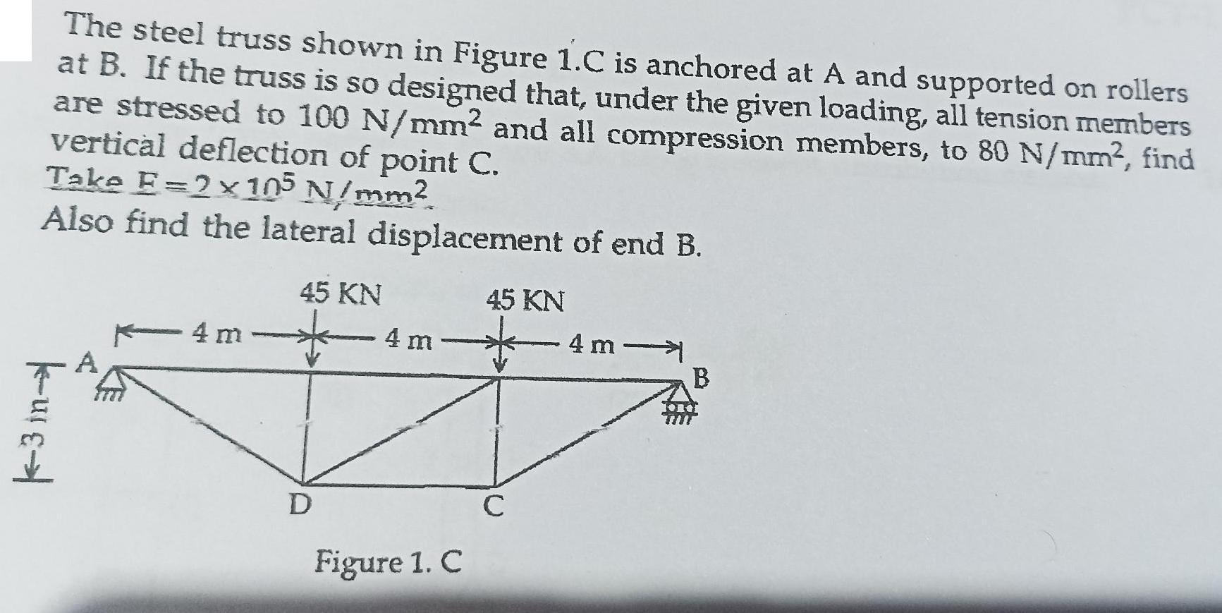
The steel truss shown in Figure 1.C is anchored at A and supported on rollers at B. If the truss is so designed that,

The steel truss shown in Figure 1.C is anchored at A and supported on rollers at B. If the truss is so designed that, under the given loading, all tension members are stressed to 100 N/mm and all compression members, to 80 N/mm, find vertical deflection of point C. Take E=2105 N/mm Also find the lateral displacement of end B. 3 A 45 KN 45 KN 4 m 4 m 4 m B D Figure 1. C C
Step by Step Solution
3.38 Rating (148 Votes )
There are 3 Steps involved in it
Step: 1
c grue that nat all tension Calcolote we vertical deflection of paind the truss is do s...
Get Instant Access to Expert-Tailored Solutions
See step-by-step solutions with expert insights and AI powered tools for academic success
Step: 2

Step: 3

Ace Your Homework with AI
Get the answers you need in no time with our AI-driven, step-by-step assistance
Get StartedRecommended Textbook for
Linear Algebra A Modern Introduction
Authors: David Poole
4th edition
1285463242, 978-1285982830, 1285982835, 978-1285463247
Students also viewed these Physics questions
Question
Answered: 1 week ago
Question
Answered: 1 week ago
Question
Answered: 1 week ago
Question
Answered: 1 week ago
Question
Answered: 1 week ago
Question
Answered: 1 week ago
Question
Answered: 1 week ago
Question
Answered: 1 week ago
Question
Answered: 1 week ago
Question
Answered: 1 week ago
Question
Answered: 1 week ago
Question
Answered: 1 week ago
Question
Answered: 1 week ago
Question
Answered: 1 week ago
Question
Answered: 1 week ago
Question
Answered: 1 week ago
Question
Answered: 1 week ago
Question
Answered: 1 week ago
Question
Answered: 1 week ago
Question
Answered: 1 week ago
Question
Answered: 1 week ago
Question
Answered: 1 week ago
View Answer in SolutionInn App


