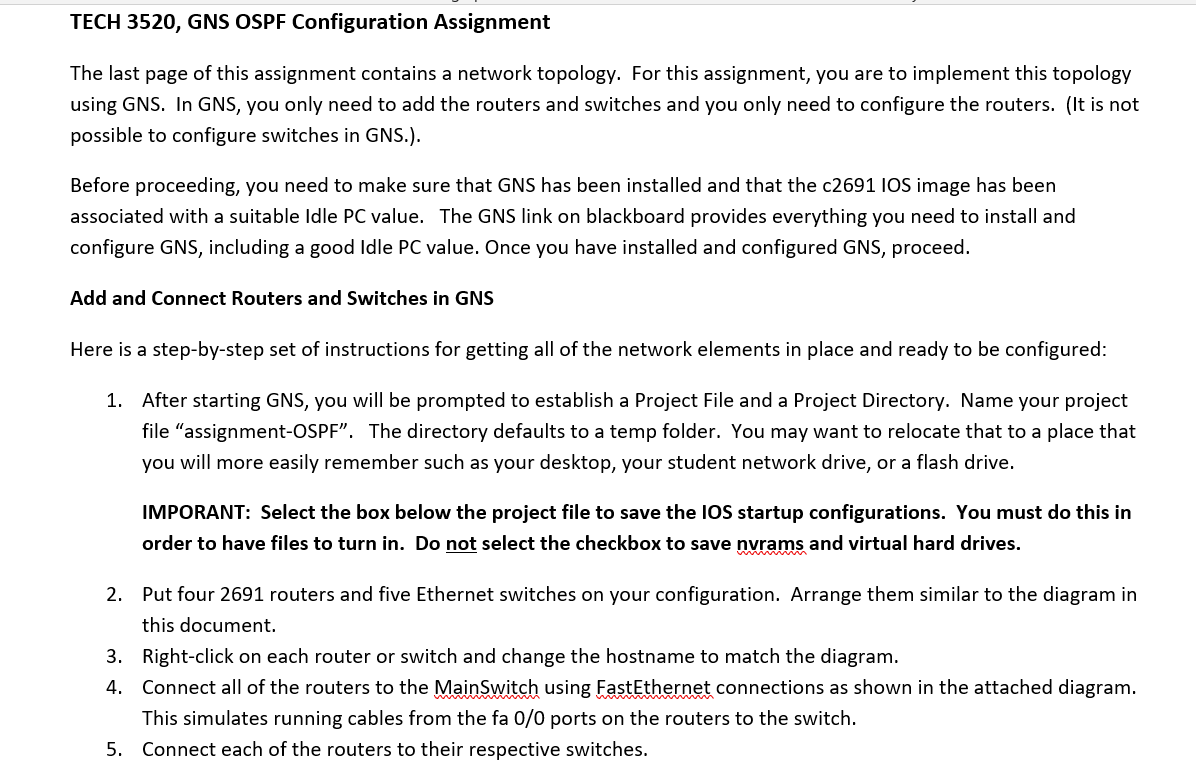
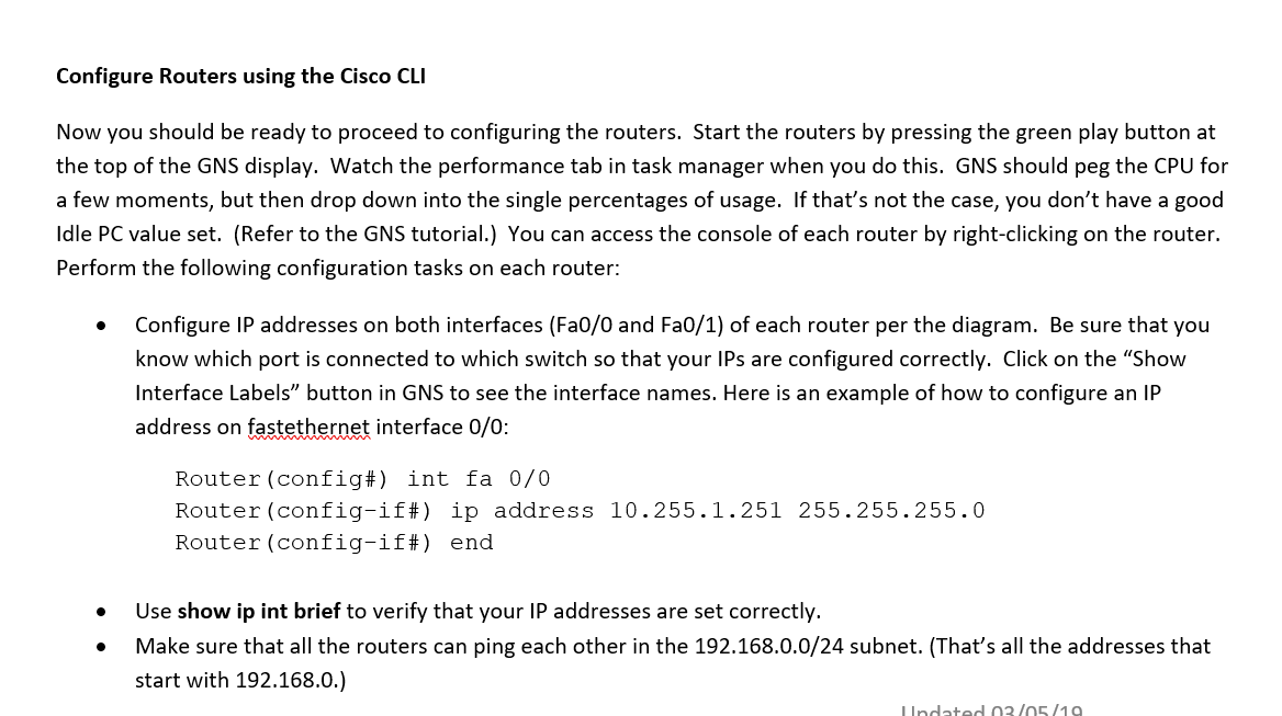
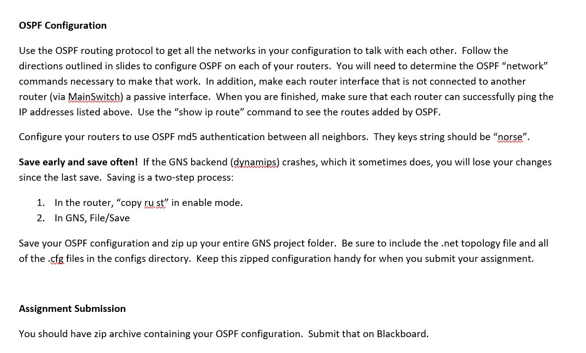
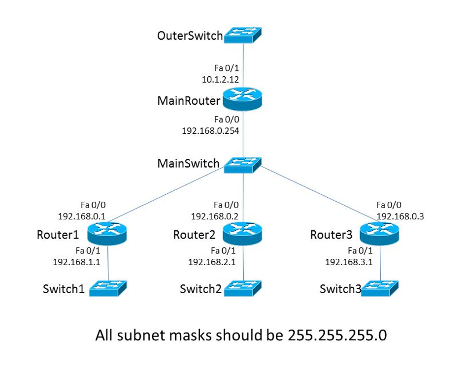
TECH 3520, GNS OSPF Configuration Assignment The last page of this assignment contains a network topology. For this assignment, you are to implement this topology using GNS. In GNS, you only need to add the routers and switches and you only need to configure the routers. (It is not possible to configure switches in GNS.). Before proceeding, you need to make sure that GNS has been installed and that the c2691 IOS image has been associated with a suitable Idle PC value. The GNS link on blackboard provides everything you need to install and configure GNS, including a good Idle PC value. Once you have installed and configured GNS, proceed. Add and Connect Routers and Switches in GNS Here is a step-by-step set of instructions for getting all of the network elements in place and ready to be configured: 1. After starting GNS, you will be prompted to establish a Project File and a Project Directory. Name your project file "assignment-OSPF". The directory defaults to a temp folder. You may want to relocate that to a place that you will more easily remember such as your desktop, your student network drive, or a flash drive. IMPORANT: Select the box below the project file to save the IOS startup configurations. You must do this in order to have files to turn in. Do not select the checkbox to save nvrams and virtual hard drives. 2. Put four 2691 routers and five Ethernet switches on your configuration. Arrange them similar to the diagram in this document. 3. Right-click on each router or switch and change the hostname to match the diagram. 4. Connect all of the routers to the MainSwitch using FastEthernet connections as shown in the attached diagram. This simulates running cables from the fa 0/0 ports on the routers to the switch. 5. Connect each of the routers to their respective switches. Configure Routers using the Cisco CLI Now you should be ready to proceed to configuring the routers. Start the routers by pressing the green play button at the top of the GNS display. Watch the performance tab in task manager when you do this. GNS should peg the CPU for a few moments, but then drop down into the single percentages of usage. If that's not the case, you don't have a good Idle PC value set. (Refer to the GNS tutorial.) You can access the console of each router by right-clicking on the router. Perform the following configuration tasks on each router: Configure IP addresses on both interfaces (Fa0/0 and Fa0/1) of each router per the diagram. Be sure that you know which port is connected to which switch so that your IPs are configured correctly. Click on the "Show Interface Labels" button in GNS to see the interface names. Here is an example of how to configure an IP address on fastethernet interface 0/0: Router (config#) int fa 0/0 Router (config-if#) ip address 10.255.1.251 255.255.255.0 Router (config-if) end Use show ip int brief to verify that your IP addresses are set correctly. Make sure that all the routers can ping each other in the 192.168.0.0/24 subnet. (That's all the addresses that start with 192.168.0.) Undated 03/05/19 OSPF Configuration Use the OSPF routing protocol to get all the networks in your configuration to talk with each other. Follow the directions outlined in slides to configure OSPF on each of your routers. You will need to determine the OSPF "network" commands necessary to make that work. In addition, make each router interface that is not connected to another router (via MainSwitch) a passive interface. When you are finished, make sure that each router can successfully ping the IP addresses listed above. Use the show ip route command to see the routes added by OSPF. Configure your routers to use OSPF md5 authentication between all neighbors. They keys string should be "norse". Save early and save often! If the GNS backend (dynamips) crashes, which it sometimes does, you will lose your changes since the last save. Saving is a two-step process: 1. In the router, copy ru st" in enable mode. 2. In GNS, File/Save Save your OSPF configuration and zip up your entire GNS project folder. Be sure to include the .net topology file and all of the .cfg files in the configs directory. Keep this zipped configuration handy for when you submit your assignment. Assignment Submission You should have zip archive containing your OSPF configuration. Submit that on Blackboard. OuterSwitch Fa 0/1 10.1.2.12 Main Router Fa 0/0 192.168.0.254 Main Switch Fa 0/0 192.168.0.1 Fa 0/0 192.168.0.2 Router1 Fa0/1 192.168.1.1 Router2 Fa0/1 192.168.2.1 Fa0/0 192.168.0.3 Router3 Fa0/1 192.168.3.1 Switch1 Switch2 Switch3 5 All subnet masks should be 255.255.255.0 TECH 3520, GNS OSPF Configuration Assignment The last page of this assignment contains a network topology. For this assignment, you are to implement this topology using GNS. In GNS, you only need to add the routers and switches and you only need to configure the routers. (It is not possible to configure switches in GNS.). Before proceeding, you need to make sure that GNS has been installed and that the c2691 IOS image has been associated with a suitable Idle PC value. The GNS link on blackboard provides everything you need to install and configure GNS, including a good Idle PC value. Once you have installed and configured GNS, proceed. Add and Connect Routers and Switches in GNS Here is a step-by-step set of instructions for getting all of the network elements in place and ready to be configured: 1. After starting GNS, you will be prompted to establish a Project File and a Project Directory. Name your project file "assignment-OSPF". The directory defaults to a temp folder. You may want to relocate that to a place that you will more easily remember such as your desktop, your student network drive, or a flash drive. IMPORANT: Select the box below the project file to save the IOS startup configurations. You must do this in order to have files to turn in. Do not select the checkbox to save nvrams and virtual hard drives. 2. Put four 2691 routers and five Ethernet switches on your configuration. Arrange them similar to the diagram in this document. 3. Right-click on each router or switch and change the hostname to match the diagram. 4. Connect all of the routers to the MainSwitch using FastEthernet connections as shown in the attached diagram. This simulates running cables from the fa 0/0 ports on the routers to the switch. 5. Connect each of the routers to their respective switches. Configure Routers using the Cisco CLI Now you should be ready to proceed to configuring the routers. Start the routers by pressing the green play button at the top of the GNS display. Watch the performance tab in task manager when you do this. GNS should peg the CPU for a few moments, but then drop down into the single percentages of usage. If that's not the case, you don't have a good Idle PC value set. (Refer to the GNS tutorial.) You can access the console of each router by right-clicking on the router. Perform the following configuration tasks on each router: Configure IP addresses on both interfaces (Fa0/0 and Fa0/1) of each router per the diagram. Be sure that you know which port is connected to which switch so that your IPs are configured correctly. Click on the "Show Interface Labels" button in GNS to see the interface names. Here is an example of how to configure an IP address on fastethernet interface 0/0: Router (config#) int fa 0/0 Router (config-if#) ip address 10.255.1.251 255.255.255.0 Router (config-if) end Use show ip int brief to verify that your IP addresses are set correctly. Make sure that all the routers can ping each other in the 192.168.0.0/24 subnet. (That's all the addresses that start with 192.168.0.) Undated 03/05/19 OSPF Configuration Use the OSPF routing protocol to get all the networks in your configuration to talk with each other. Follow the directions outlined in slides to configure OSPF on each of your routers. You will need to determine the OSPF "network" commands necessary to make that work. In addition, make each router interface that is not connected to another router (via MainSwitch) a passive interface. When you are finished, make sure that each router can successfully ping the IP addresses listed above. Use the show ip route command to see the routes added by OSPF. Configure your routers to use OSPF md5 authentication between all neighbors. They keys string should be "norse". Save early and save often! If the GNS backend (dynamips) crashes, which it sometimes does, you will lose your changes since the last save. Saving is a two-step process: 1. In the router, copy ru st" in enable mode. 2. In GNS, File/Save Save your OSPF configuration and zip up your entire GNS project folder. Be sure to include the .net topology file and all of the .cfg files in the configs directory. Keep this zipped configuration handy for when you submit your assignment. Assignment Submission You should have zip archive containing your OSPF configuration. Submit that on Blackboard. OuterSwitch Fa 0/1 10.1.2.12 Main Router Fa 0/0 192.168.0.254 Main Switch Fa 0/0 192.168.0.1 Fa 0/0 192.168.0.2 Router1 Fa0/1 192.168.1.1 Router2 Fa0/1 192.168.2.1 Fa0/0 192.168.0.3 Router3 Fa0/1 192.168.3.1 Switch1 Switch2 Switch3 5 All subnet masks should be 255.255.255.0