Answered step by step
Verified Expert Solution
Question
1 Approved Answer
The below figures show a simple computer chip package, such as a diode. Fine wires connect the silicon die to metallic leads that are


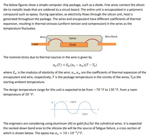
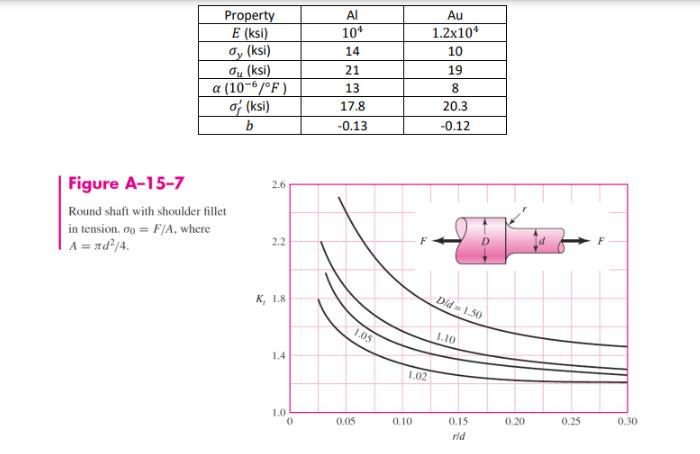
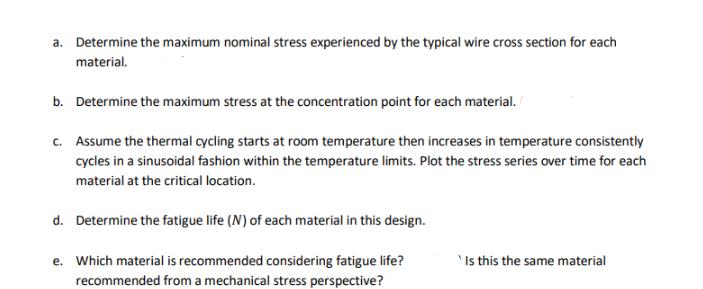
The below figures show a simple computer chip package, such as a diode. Fine wires connect the silicon die to metallic leads that are soldered to a circuit board. The entire unit is encapsulated in a polymeric compound such as epoxy. During operation, as electricity flows through the silicon unit, heat is generated throughout the package. The wires and encapsulant have different coefficients of thermal expansion, resulting in thermal stresses (uniform tension and compression) in the wires as the temperature fluctuates. Lead Wire Epoxy Diode The nominal stress due to thermal sources in the wire is given by ow (T) = Ew (de-aw) (T-To) where Ew is the modulus of elasticity of the wire; e, aw are the coefficients of thermal expansion of the encapsulant and wire, respectively; T is the package temperature in the vicinity of the wires, To is the starting ambient temperature. Wire Bond The design temperature range for this unit is expected to be from -70 F to 130 F, from a room temperature of 30F. 130F na -70F The engineers are considering using aluminum (Al) or gold (Au) for the cylindrical wires. It is expected the necked-down bond area to the silicone die will be the source of fatigue failure, a cross section of which is shown below. The epoxy has a = 10 + 10-6/F. Epoxy 0.001 in Wire Solder R 0.00005 in Property E (ksi) ay (ksi) au (ksi) a (10-6/F) of (ksi) b Figure A-15-7 Round shaft with shoulder fillet in tension. 00= F/A, where A = nd/4. 2.6 2.2 K, 1.8 1.4 1.0 0 Al 104 14 21 13 17.8 -0.13 1.05 0,05 1.02 0.10 Au 1.2x10 10 19 8 20.3 -0.12 Did 1.50 1.10 0.15 rid 0.20 0.25 0.30 a. Determine the maximum nominal stress experienced by the typical wire cross section for each material. b. Determine the maximum stress at the concentration point for each material. c. Assume the thermal cycling starts at room temperature then increases in temperature consistently cycles in a sinusoidal fashion within the temperature limits. Plot the stress series over time for each material at the critical location. d. Determine the fatigue life (N) of each material in this design. e. Which material is recommended considering fatigue life? recommended from a mechanical stress perspective? Is this the same material The below figures show a simple computer chip package, such as a diode. Fine wires connect the silicon die to metallic leads that are soldered to a circuit board. The entire unit is encapsulated in a polymeric compound such as epoxy. During operation, as electricity flows through the silicon unit, heat is generated throughout the package. The wires and encapsulant have different coefficients of thermal expansion, resulting in thermal stresses (uniform tension and compression) in the wires as the temperature fluctuates. Lead Wire Epoxy Diode The nominal stress due to thermal sources in the wire is given by ow (T) = Ew (de-aw) (T-To) where Ew is the modulus of elasticity of the wire; e, aw are the coefficients of thermal expansion of the encapsulant and wire, respectively; T is the package temperature in the vicinity of the wires, To is the starting ambient temperature. Wire Bond The design temperature range for this unit is expected to be from -70 F to 130 F, from a room temperature of 30F. 130F na -70F The engineers are considering using aluminum (Al) or gold (Au) for the cylindrical wires. It is expected the necked-down bond area to the silicone die will be the source of fatigue failure, a cross section of which is shown below. The epoxy has a = 10 + 10-6/F. Epoxy 0.001 in Wire Solder R 0.00005 in Property E (ksi) ay (ksi) Tu (ksi) a (10-6/F) of (ksi) b Figure A-15-7 Round shaft with shoulder fillet in tension. 00= F/A, where A = nd/4. 2.6 2.2 K, 1.8 1.4 1.0 0 Al 104 14 21 13 17.8 -0.13 1.05 0,05 1.02 0.10 Au 1.2x10 10 19 8 20.3 -0.12 Did 1.50 1.10 0.15 rid 0.20 0.25 0.30 a. Determine the maximum nominal stress experienced by the typical wire cross section for each material. b. Determine the maximum stress at the concentration point for each material. c. Assume the thermal cycling starts at room temperature then increases in temperature consistently cycles in a sinusoidal fashion within the temperature limits. Plot the stress series over time for each material at the critical location. d. Determine the fatigue life (N) of each material in this design. e. Which material is recommended considering fatigue life? recommended from a mechanical stress perspective? Is this the same material
Step by Step Solution
★★★★★
3.39 Rating (152 Votes )
There are 3 Steps involved in it
Step: 1
The provided images showcase a computer chip package where fine wires connect the silicon die to metallic leads on a circuit board There are several parts to the problem and Ill address them step by s...
Get Instant Access to Expert-Tailored Solutions
See step-by-step solutions with expert insights and AI powered tools for academic success
Step: 2

Step: 3

Ace Your Homework with AI
Get the answers you need in no time with our AI-driven, step-by-step assistance
Get Started


