Question
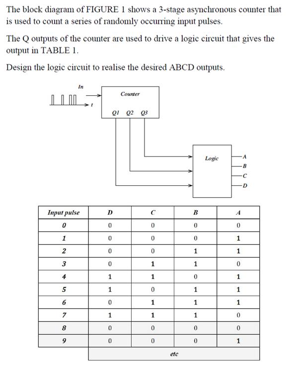
The block diagram of FIGURE 1 shows a 3-stage asynchronous counter that is used to count a series of randomly occurring input pulses. The

The block diagram of FIGURE 1 shows a 3-stage asynchronous counter that is used to count a series of randomly occurring input pulses. The Q outputs of the counter are used to drive a logic circuit that gives the output in TABLE 1. Design the logic circuit to realise the desired ABCD outputs. Input pulse 0 1 2 3 4 5 6 7 8 9 t 01 02 03 D 0 0 0 0 Counter 1 1 0 1 0 0 C 0 0 0 1 1 0 1 1 0 0 etc B 0 0 1 1 0 1 1 1 0 0 Logic A B C -D A 0 1 1 0 1 1 1 0 0 1
Step by Step Solution
3.47 Rating (150 Votes )
There are 3 Steps involved in it
Step: 1
Input 0 2 3 00 00 Q 00 0 1 0 0 using D Sabo too 0 80 ...
Get Instant Access to Expert-Tailored Solutions
See step-by-step solutions with expert insights and AI powered tools for academic success
Step: 2

Step: 3

Ace Your Homework with AI
Get the answers you need in no time with our AI-driven, step-by-step assistance
Get StartedRecommended Textbook for
Digital Systems Principles And Application
Authors: Ronald Tocci, Neal Widmer, Gregory Moss
12th Edition
0134220137, 978-0134220130
Students also viewed these Organizational Behavior questions
Question
Answered: 1 week ago
Question
Answered: 1 week ago
Question
Answered: 1 week ago
Question
Answered: 1 week ago
Question
Answered: 1 week ago
Question
Answered: 1 week ago
Question
Answered: 1 week ago
Question
Answered: 1 week ago
Question
Answered: 1 week ago
Question
Answered: 1 week ago
Question
Answered: 1 week ago
Question
Answered: 1 week ago
Question
Answered: 1 week ago
Question
Answered: 1 week ago
Question
Answered: 1 week ago
Question
Answered: 1 week ago
Question
Answered: 1 week ago
Question
Answered: 1 week ago
Question
Answered: 1 week ago
Question
Answered: 1 week ago
Question
Answered: 1 week ago
Question
Answered: 1 week ago
View Answer in SolutionInn App


