Answered step by step
Verified Expert Solution
Question
1 Approved Answer
The circuit diagram for an FSM is given below. The FSM is defined using 2 states: Q, and Q2, an input signal (In) and an
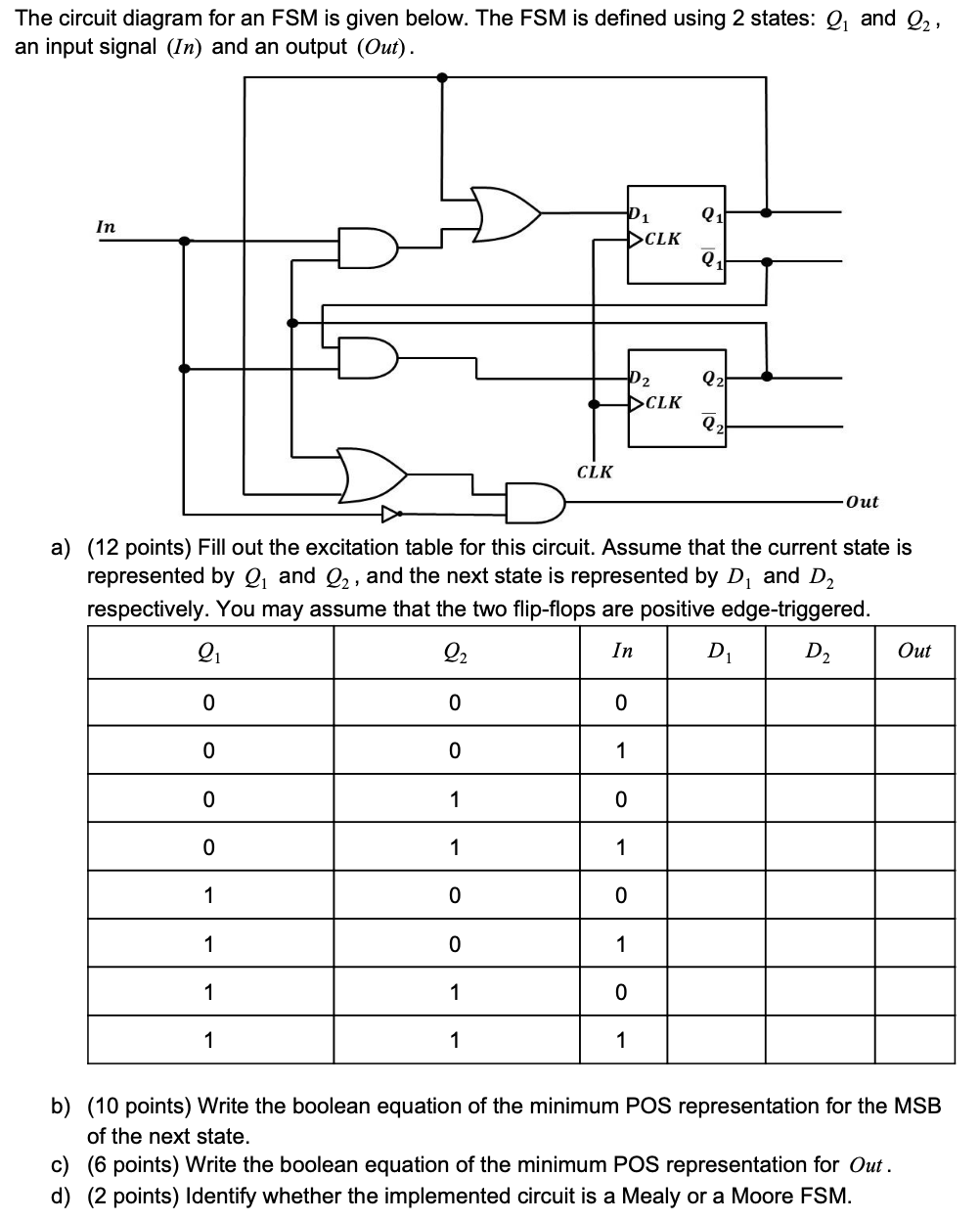
The circuit diagram for an FSM is given below. The FSM is defined using 2 states: Q, and Q2, an input signal (In) and an output (Out). Q1 In P1 DCLK Q Q2 02 CLK Q2 CLK Out a) (12 points) Fill out the excitation table for this circuit. Assume that the current state is represented by Q, and Q2, and the next state is represented by D, and D2 respectively. You may assume that the two flip-flops are positive edge-triggered. Q 22 In D D2 Out 0 0 0 0 0 1 0 1 0 0 1 1 1 0 0 1 0 1 1 1 0 1 1 1 b) (10 points) Write the boolean equation of the minimum POS representation for the MSB of the next state. c) (6 points) Write the boolean equation of the minimum POS representation for Out. d) (2 points) Identify whether the implemented circuit is a Mealy or a Moore FSM
Step by Step Solution
There are 3 Steps involved in it
Step: 1
Get Instant Access to Expert-Tailored Solutions
See step-by-step solutions with expert insights and AI powered tools for academic success
Step: 2
Step: 3
Ace Your Homework with AI
Get the answers you need in no time with our AI-driven, step-by-step assistance
Get Started