Answered step by step
Verified Expert Solution
Question
1 Approved Answer
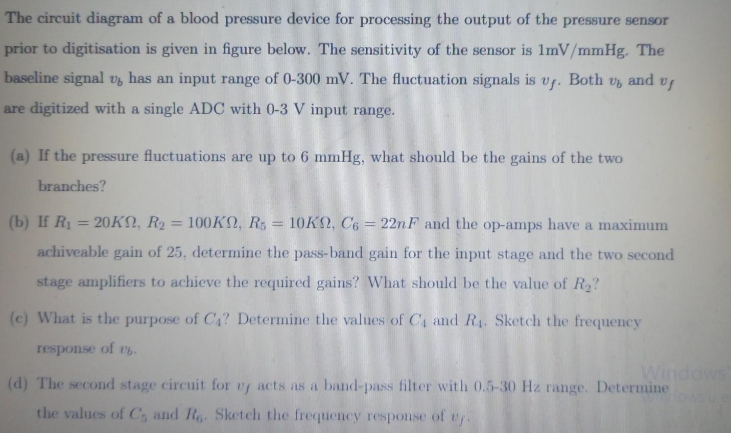
The circuit diagram of a blood pressure device for processing the output of the pressure sensor prior to digitisation is given in figure below. The


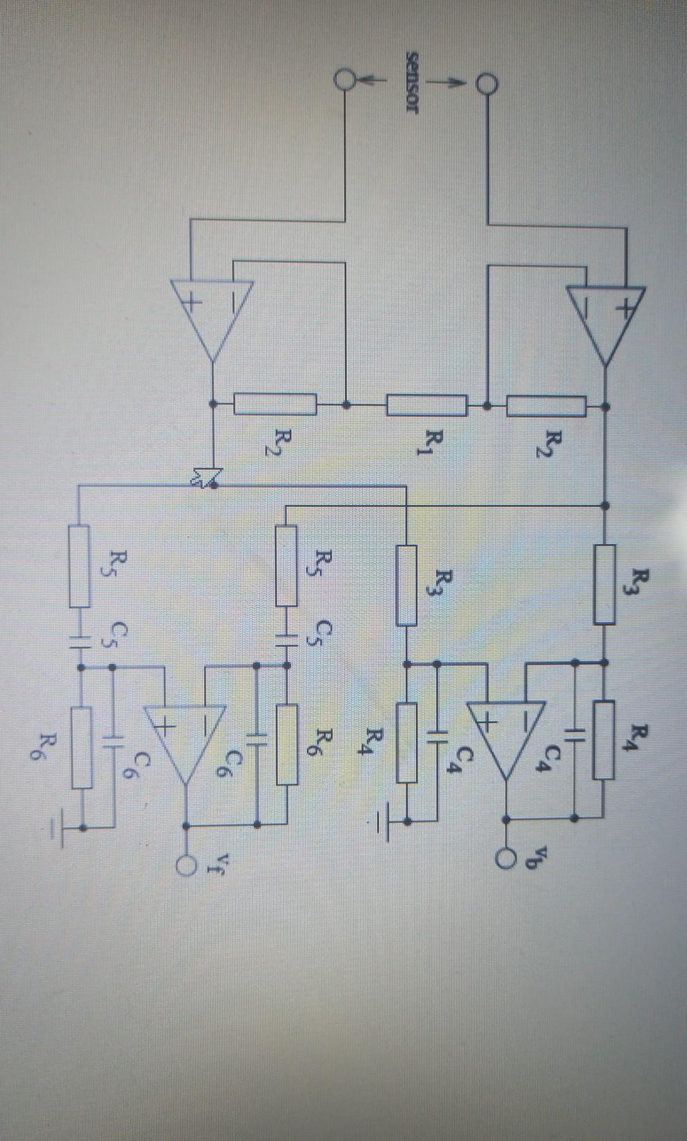
The circuit diagram of a blood pressure device for processing the output of the pressure sensor prior to digitisation is given in figure below. The sensitivity of the sensor is 1mV/mmHg. The baseline signal vy has an input range of 0-300 mV. The fluctuation signals is uf Both and uf are digitized with a single ADC with 0-3 V input range. V (a) If the pressure fluctuations are up to 6 mmHg, what should be the gains of the two branches? (b) If Ri = 20K1, R2 = 100K2, R; = 10K2, C6 = 22nF and the op-amps have a maximum achiveable gain of 25. determine the pass-band gain for the input stage and the two second stage amplifiers to achieve the required gains? What should be the value of R ? (c) What is the purpose of Ca? Determine the values of C, and R. Sketch the frequency response of u (d) The second stage circuit for vy acts as a band-pass filter with 0.5-30 Hz range. Determine the values of C, and R. Sketch the frequency response of up. R3 RA R2 CA Vb CA R R3 sensor RA Rs Cs Ro R, HH C6 Ve C6 Rs C5 Ro
Step by Step Solution
There are 3 Steps involved in it
Step: 1

Get Instant Access to Expert-Tailored Solutions
See step-by-step solutions with expert insights and AI powered tools for academic success
Step: 2

Step: 3

Ace Your Homework with AI
Get the answers you need in no time with our AI-driven, step-by-step assistance
Get Started


