Answered step by step
Verified Expert Solution
Question
1 Approved Answer
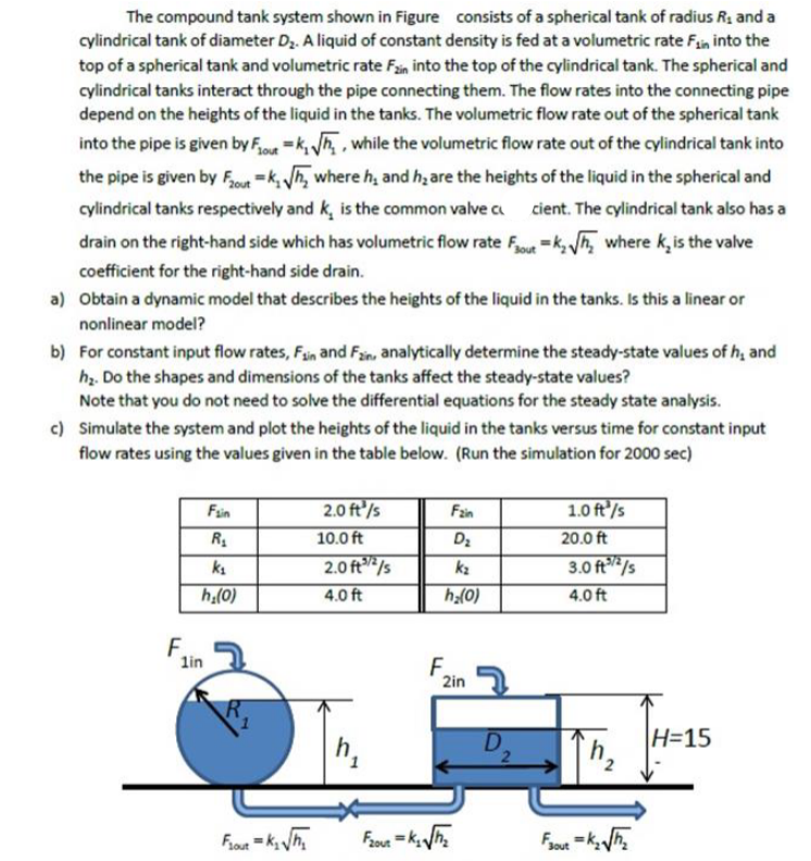
The compound tank system shown in Figure consists of a spherical tank of radius R 1 and a cylindrical tank of diameter D 2 .
The compound tank system shown in Figure consists of a spherical tank of radius and a
cylindrical tank of diameter A liquid of constant density is fed at a volumetric rate into the
top of a spherical tank and volumetric rate into the top of the cylindrical tank. The spherical and
cylindrical tanks interact through the pipe connecting them. The flow rates into the connecting pipe
depend on the heights of the liquid in the tanks. The volumetric flow rate out of the spherical tank
into the pipe is given by while the volumetric flow rate out of the cylindrical tank into
the pipe is given by where and are the heights of the liquid in the spherical and
cylindrical tanks respectively and is the common valve cient. The cylindrical tank also has a
drain on the righthand side which has volumetric flow rate where is the valve
coefficient for the righthand side drain.
a Obtain a dynamic model that describes the heights of the liquid in the tanks. Is this a linear or
nonlinear model?
b For constant input flow rates, and analytically determine the steadystate values of and
Do the shapes and dimensions of the tanks affect the steadystate values?
Note that you do not need to solve the differential equations for the steady state analysis.
c Simulate the system and plot the heights of the liquid in the tanks versus time for constant input
flow rates using the values given in the table below. Run the simulation for

Step by Step Solution
There are 3 Steps involved in it
Step: 1

Get Instant Access to Expert-Tailored Solutions
See step-by-step solutions with expert insights and AI powered tools for academic success
Step: 2

Step: 3

Ace Your Homework with AI
Get the answers you need in no time with our AI-driven, step-by-step assistance
Get Started


