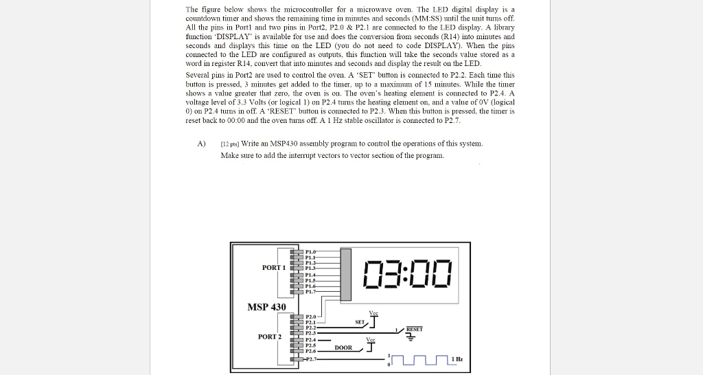
The figure below shows the microcontroller for a microwave oven. The LED digital display is a
countdown timer and shows the remaining time in minutes and seconds (MM:SS) until the unit turns off.
All the pins in Port1 and two pins in Port2, P2.0 & P2.1 are connected to the LED display.
A library function DISPLAY is available for use and does the conversion from seconds (R14) into minutes and
seconds and displays this time on the LED (you do not need to code DISPLAY).
When the pins connected to the LED are configured as outputs, this function will take the seconds value stored as a
word in register R14, convert that into minutes and seconds and display the result on the LED. Several pins in Port2 are used to control the oven. A SET button is connected to P2.2. Each time this button is pressed, 3 minutes get added to the timer, up to a maximum of 15 minutes. While the timer
shows a value greater that zero, the oven is on. The ovens heating element is connected to P2.4. A voltage level of 3.3 Volts (or logical 1) on P2.4 turns the heating element on, and a value of 0V (logical 0) on P2.4 turns in off. A RESET button is connected to P2.3. When this button is pressed, the timer is
reset back to 00:00 and the oven turns off. A 1 Hz stable oscillator is connected to P2.7.
A)Write an MSP430 assembly program to control the operations of this system. Make sure to add the interrupt vectors to vector section of the program.
The figure below shows the microcontroller for a microwave oven. The LED digital display is a countdown timer and shows the remaining time in minutes and seconds (MM:SS) until the unit turns off. All the pins in Port and two pins in Port2, P2.0 & P2.1 are connected to the LED display. A library function DISPLAY, is available for use and does the conversion from seconds (R14) Into minutes and seconds and displays this time on the LED (you do not need to code DISPLAY)wien the pins connected to the LED are configured as outputs, this fnction will take the seconds value stored as a word in register R14, convert that into minutes and seconds and display the result on the LED Several pins in Port2 are used to control the oven. A 'SET button is connected to P2.2. Each time this button is pressed, 3 minutes get added to the timer, up to a maximu of 15 minutes. While the timer shows a value greater that zero, the oven is on. The oven's heating elemen is connected to P2.4. A voltage level of 3.3 Volts (or logical 1) on P2.4 turns the heating element on, and a value of OV (logical 0) on P2.4 tums in off. A 'RESET button is connected to P2.3. When this button is pressed, the timer is reset back to 00:00 and the oven tuns off. A 1 Hz stablescllator is connected to P2.7 A) 2 ts) Write an MSP430 assembly program to control the operations of this system Make sure to add the interrupt vectors to vector section of the program PI PI PORT 1 P1 MSP 430 P2.0 SET P2.2 P2.3 P24 PORT 2 DOOR The figure below shows the microcontroller for a microwave oven. The LED digital display is a countdown timer and shows the remaining time in minutes and seconds (MM:SS) until the unit turns off. All the pins in Port and two pins in Port2, P2.0 & P2.1 are connected to the LED display. A library function DISPLAY, is available for use and does the conversion from seconds (R14) Into minutes and seconds and displays this time on the LED (you do not need to code DISPLAY)wien the pins connected to the LED are configured as outputs, this fnction will take the seconds value stored as a word in register R14, convert that into minutes and seconds and display the result on the LED Several pins in Port2 are used to control the oven. A 'SET button is connected to P2.2. Each time this button is pressed, 3 minutes get added to the timer, up to a maximu of 15 minutes. While the timer shows a value greater that zero, the oven is on. The oven's heating elemen is connected to P2.4. A voltage level of 3.3 Volts (or logical 1) on P2.4 turns the heating element on, and a value of OV (logical 0) on P2.4 tums in off. A 'RESET button is connected to P2.3. When this button is pressed, the timer is reset back to 00:00 and the oven tuns off. A 1 Hz stablescllator is connected to P2.7 A) 2 ts) Write an MSP430 assembly program to control the operations of this system Make sure to add the interrupt vectors to vector section of the program PI PI PORT 1 P1 MSP 430 P2.0 SET P2.2 P2.3 P24 PORT 2 DOOR


