Question
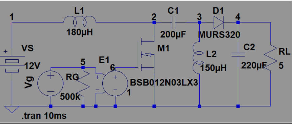
The final design should follow the circuit below: (the values don't matter) Design a SEPIC dc-dc converter in Fig.1 to meet the following specifications. Input

The final design should follow the circuit below: (the values don't matter)

Design a SEPIC dc-dc converter in Fig.1 to meet the following specifications. Input DC voltage V = 12 V Average output voltage V = 98 V Peak-to-peak ripple on the output ripple AV 5% of the average output voltage Peak-to-peak ripple on the inductor (L) current AI 5% of the average inductor current Average load current I = 0.5 A Switching frequency f. = 20 kHz. 000 SEPIC G= 52 Fig. 1 SEPIC converter Use an NMOS as a switch for LTspice or PSpice or Multisim simulation (Note the gate voltage must be applied between the gate and the source terminals though a voltage-controlled voltage-source as an isolating unit). MOSFET Type: BSB012N03LX3 Power Diode type: MURS320
Step by Step Solution
There are 3 Steps involved in it
Step: 1

Get Instant Access to Expert-Tailored Solutions
See step-by-step solutions with expert insights and AI powered tools for academic success
Step: 2

Step: 3

Ace Your Homework with AI
Get the answers you need in no time with our AI-driven, step-by-step assistance
Get StartedRecommended Textbook for
Analysis and Design of Analog Integrated Circuits
Authors: Paul R. Gray, Paul J. Hurst Stephen H. Lewis, Robert G. Meyer
5th edition
1111827052, 1285401107, 9781285401102 , 978-0470245996
Students also viewed these Electrical Engineering questions
Question
Answered: 1 week ago
Question
Answered: 1 week ago
Question
Answered: 1 week ago
Question
Answered: 1 week ago
Question
Answered: 1 week ago
Question
Answered: 1 week ago
Question
Answered: 1 week ago
Question
Answered: 1 week ago
Question
Answered: 1 week ago
Question
Answered: 1 week ago
Question
Answered: 1 week ago
Question
Answered: 1 week ago
Question
Answered: 1 week ago
Question
Answered: 1 week ago
Question
Answered: 1 week ago
Question
Answered: 1 week ago
Question
Answered: 1 week ago
Question
Answered: 1 week ago
Question
Answered: 1 week ago
Question
Answered: 1 week ago
Question
Answered: 1 week ago
View Answer in SolutionInn App


