Answered step by step
Verified Expert Solution
Question
1 Approved Answer
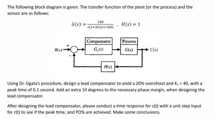
The following block diagram is given. The transfer function of the plant (or the process) and the sensor are as follows: R(s) G(s): 100

The following block diagram is given. The transfer function of the plant (or the process) and the sensor are as follows: R(s) G(s): 100 s(s+36) (s+100) Compensator G,(s) H(s) H(s) = 1 Process G(s) C(s) Using Dr. Ogata's procedure, design a lead compensator to yield a 20% overshoot and K, = 40, with a peak time of 0.1 second. Add an extra 10 degrees to the necessary phase margin, when designing the lead compensator. After designing the lead compensator, please conduct a time response for c(t) with a unit step input for r(t) to see if the peak time, and PO% are achieved. Make some conclusions.
Step by Step Solution
★★★★★
3.42 Rating (152 Votes )
There are 3 Steps involved in it
Step: 1
Here are the steps to design a lead compensator for the given system 1 Given Process transfer functi...
Get Instant Access to Expert-Tailored Solutions
See step-by-step solutions with expert insights and AI powered tools for academic success
Step: 2

Step: 3

Ace Your Homework with AI
Get the answers you need in no time with our AI-driven, step-by-step assistance
Get Started


