Answered step by step
Verified Expert Solution
Question
1 Approved Answer
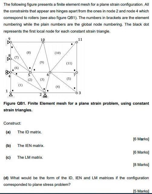
The following figure presents a finite element mesh for a plane strain configuration. All the constraints that appear are hinges apart from the ones

The following figure presents a finite element mesh for a plane strain configuration. All the constraints that appear are hinges apart from the ones in node 2 and node 4 which correspond to rollers (see also figure QB1). The numbers in brackets are the element numbering while the plain numbers are the global node numbering. The black dot represents the first local node for each constant strain triangle. 8.00 1 (b) (1) Construct: (a) (C) 85 (2) (9) (3) 28 Figure QB1. Finite Element mesh for a plane strain problem, using constant strain triangles. The ID matrix. The IEN matrix. (10) The LM matrix. (11) (5) 3 [6 Marks] [6 Marks] [8 Marks] (d) What would be the form of the ID, IEN and LM matrices if the configuration corresponded to plane stress problem? [5 Marks]
Step by Step Solution
★★★★★
3.41 Rating (148 Votes )
There are 3 Steps involved in it
Step: 1
Answer a The ID Matrix The ID matrix is used to assign global degrees of freedom DOFs to each node i...
Get Instant Access to Expert-Tailored Solutions
See step-by-step solutions with expert insights and AI powered tools for academic success
Step: 2

Step: 3

Ace Your Homework with AI
Get the answers you need in no time with our AI-driven, step-by-step assistance
Get Started


