Question
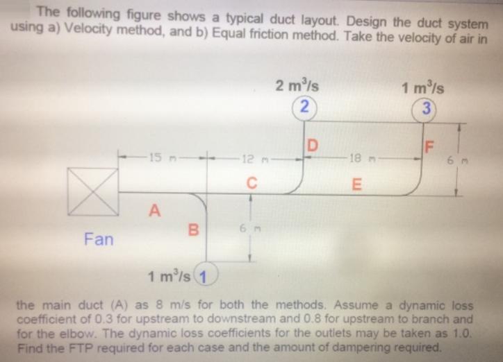
The following figure shows a typical duct layout. Design the duct system using a) Velocity method, and b) Equal friction method. Take the velocity

The following figure shows a typical duct layout. Design the duct system using a) Velocity method, and b) Equal friction method. Take the velocity of air in 2 m/s 1 m/s 3 2 D F 6 m 15 m 12 m- 18 C 6 m Fan 1 m/s 1 the main duct (A) as 8 m/s for both the methods. Assume a dynamic loss coefficient of 0.3 for upstream to downstream and 0.8 for upstream to branch and for the elbow. The dynamic loss coefficients for the outlets may be taken as 1.0. Find the FTP required for each case and the amount of dampering required.
Step by Step Solution
3.37 Rating (156 Votes )
There are 3 Steps involved in it
Step: 1
Burex chop shan OO and prususendoops inuition O ...
Get Instant Access to Expert-Tailored Solutions
See step-by-step solutions with expert insights and AI powered tools for academic success
Step: 2

Step: 3

Ace Your Homework with AI
Get the answers you need in no time with our AI-driven, step-by-step assistance
Get StartedRecommended Textbook for
Computer Networking A Top-Down Approach
Authors: James F. Kurose, Keith W. Ross
5th edition
136079679, 978-0136079675
Students also viewed these Computer Network questions
Question
Answered: 1 week ago
Question
Answered: 1 week ago
Question
Answered: 1 week ago
Question
Answered: 1 week ago
Question
Answered: 1 week ago
Question
Answered: 1 week ago
Question
Answered: 1 week ago
Question
Answered: 1 week ago
Question
Answered: 1 week ago
Question
Answered: 1 week ago
Question
Answered: 1 week ago
Question
Answered: 1 week ago
Question
Answered: 1 week ago
Question
Answered: 1 week ago
Question
Answered: 1 week ago
Question
Answered: 1 week ago
Question
Answered: 1 week ago
Question
Answered: 1 week ago
Question
Answered: 1 week ago
Question
Answered: 1 week ago
Question
Answered: 1 week ago
Question
Answered: 1 week ago
View Answer in SolutionInn App


