Question
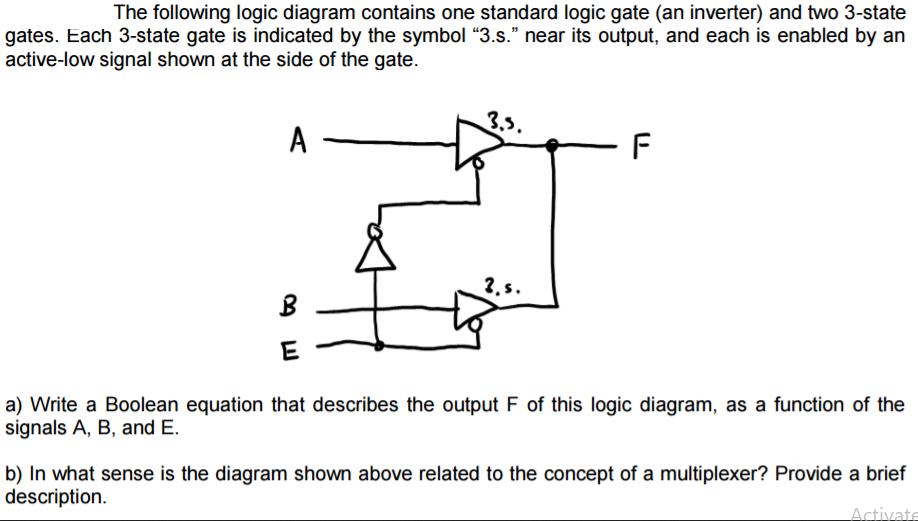
The following logic diagram contains one standard logic gate (an inverter) and two 3-state gates. Each 3-state gate is indicated by the symbol 3.s.

The following logic diagram contains one standard logic gate (an inverter) and two 3-state gates. Each 3-state gate is indicated by the symbol "3.s." near its output, and each is enabled by an active-low signal shown at the side of the gate. A B E 3.5. 2, s. F a) Write a Boolean equation that describes the output F of this logic diagram, as a function of the signals A, B, and E. b) In what sense is the diagram shown above related to the concept of a multiplexer? Provide a brief description. Activate
Step by Step Solution
3.45 Rating (152 Votes )
There are 3 Steps involved in it
Step: 1
Ans aLooking at the diagram F AE BE b As per multiplexer operation that is out of man...
Get Instant Access to Expert-Tailored Solutions
See step-by-step solutions with expert insights and AI powered tools for academic success
Step: 2

Step: 3

Ace Your Homework with AI
Get the answers you need in no time with our AI-driven, step-by-step assistance
Get StartedRecommended Textbook for
Fundamentals of Digital Logic and Microcontrollers
Authors: M. Rafiquzzaman
6th edition
1-118-85579-9, 1118855795, 9781118969304, 978-1118855799
Students also viewed these Programming questions
Question
Answered: 1 week ago
Question
Answered: 1 week ago
Question
Answered: 1 week ago
Question
Answered: 1 week ago
Question
Answered: 1 week ago
Question
Answered: 1 week ago
Question
Answered: 1 week ago
Question
Answered: 1 week ago
Question
Answered: 1 week ago
Question
Answered: 1 week ago
Question
Answered: 1 week ago
Question
Answered: 1 week ago
Question
Answered: 1 week ago
Question
Answered: 1 week ago
Question
Answered: 1 week ago
Question
Answered: 1 week ago
Question
Answered: 1 week ago
Question
Answered: 1 week ago
Question
Answered: 1 week ago
Question
Answered: 1 week ago
Question
Answered: 1 week ago
Question
Answered: 1 week ago
Question
Answered: 1 week ago
View Answer in SolutionInn App


