Answered step by step
Verified Expert Solution
Question
1 Approved Answer
The following state diagram in Fig. 3 is a finite state machine (FSM) showing seven outputs of 4-bit width. When enable (CE) is '0', it
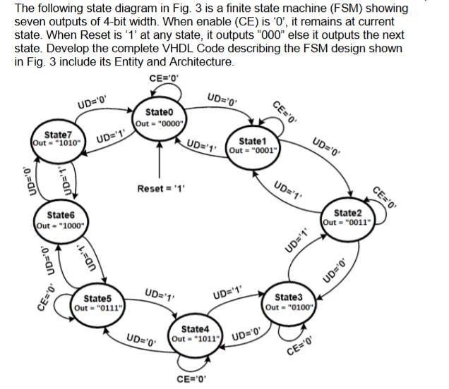
The following state diagram in Fig. 3 is a finite state machine (FSM) showing seven outputs of 4-bit width. When enable (CE) is '0', it remains at current state. When Reset is '1' at any state, it outputs "000" else it outputs the next state. Develop the complete VHDL Code describing the FSM design shown in Fig. 3 include its Entity and Architecture. CE='0' UD='0' UD='0' CE='0' Stateo Out="0000") State7 Out "1010) UD='1' UD='t. (Out="0001") State1 UD='0' UD='0 b.=an Reset = '1' UD='1' CE='0' Statet Out = "1000" State2 Out = "0011") = UD='1' 0.=an UD='1' UD='0' CE='0' UD='1' UD='1' State5 Out = "0111") State3 Out - "0100") - State4 UD='0 Out - 2011) UD=0 CE='0' CE='0
Step by Step Solution
There are 3 Steps involved in it
Step: 1
Get Instant Access to Expert-Tailored Solutions
See step-by-step solutions with expert insights and AI powered tools for academic success
Step: 2
Step: 3
Ace Your Homework with AI
Get the answers you need in no time with our AI-driven, step-by-step assistance
Get Started