Answered step by step
Verified Expert Solution
Question
1 Approved Answer
The frameworks are mounted into two supports. One support allows pivoting only (pinned), the other support allows pivoting and linear translation (free or roller)

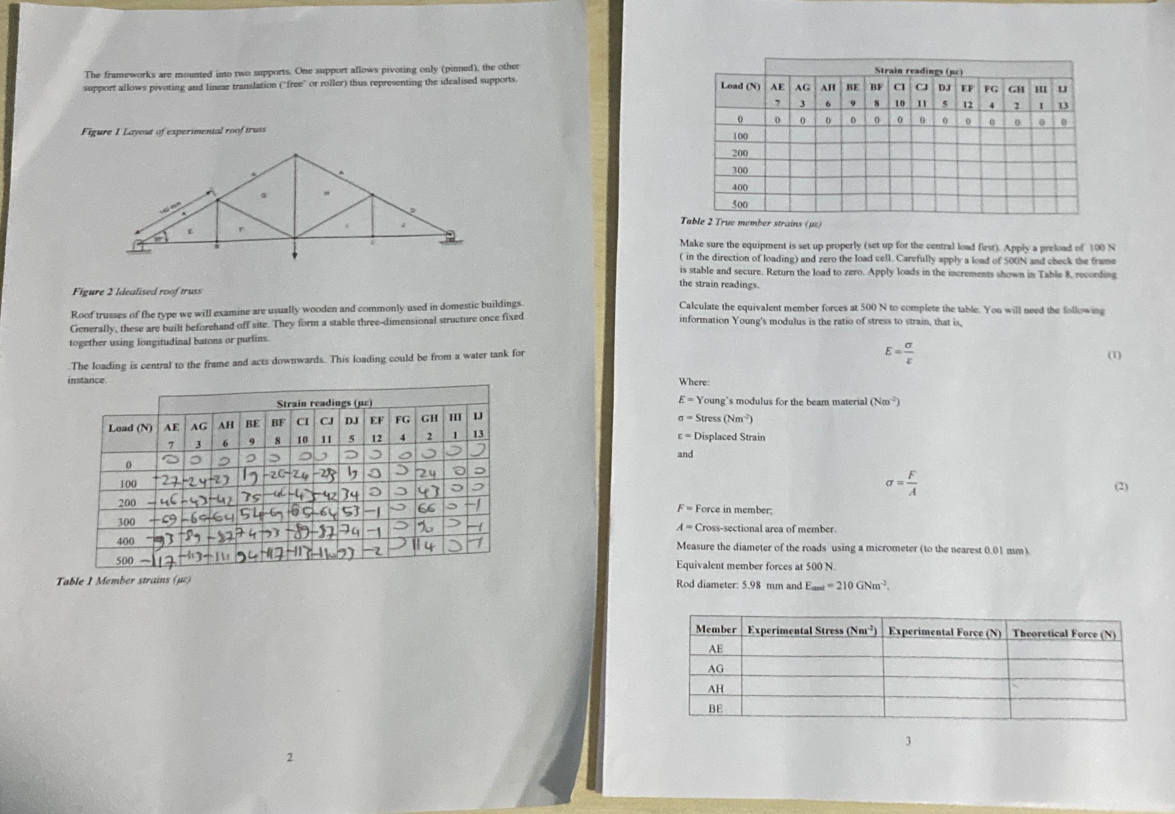
The frameworks are mounted into two supports. One support allows pivoting only (pinned), the other support allows pivoting and linear translation (free or roller) thus representing the idealised supports. Figure 1 Layout of experimental roof truss Strain readings (p) Load (N) AE AG AH BE 5 7 3 9 8 10 0 = BF C C DJ EF FG GH HIU 5 12 4 2 I 13 0 0 0 0 0 0 0 0 0 0 0 0 0 100 200 300 400 500 Figure 2 Idealised roof truss Roof trusses of the type we will examine are usually wooden and commonly used in domestic buildings. Generally, these are built beforehand off site. They form a stable three-dimensional structure once fixed together using longitudinal batons or purlins. The loading is central to the frame and acts downwards. This loading could be from a water tank for instance. Strain readings (c) Load (N) AE AG AH BE BF CI CJ DJ EF FG GH HI IJ 7 3 6 9 10 8 11 5 12 4 2 1 13 9 0 24 100 200 300 002 00 +27-24-23 17-26-24-258173 146-43-42/75-46-442 343 343 +69-696454-665-6453- 40039-274-73-89-57-747 500-> 1175 13-11154-17-113-11-03-2 Table 1 Member strains (pc) 66 20 1200 Table 2 True member strains (p) Make sure the equipment is set up properly (set up for the central load first). Apply a preload of 100 N (in the direction of loading) and zero the load cell. Carefully apply a load of 500N and check the frame is stable and secure. Return the load to zero. Apply loads in the increments shown in Table 8, recording the strain readings. Calculate the equivalent member forces at 500 N to complete the table. You will need the following information Young's modulus is the ratio of stress to strain, that is, Where: E= E-Young's modulus for the bear material (Nm) Stress (Nm) E=Displaced Strain and F=Force in member; A Cross-sectional area of member. Measure the diameter of the roads using a micrometer (to the nearest 0.01 mm). Equivalent member forces at 500 N. Rod diameter: 5.98 mm and Earl 210 GNm (0) e) 2 Member Experimental Stress (Nm) Experimental Force (N) Theoretical Force (N) AE AG AH BE
Step by Step Solution
There are 3 Steps involved in it
Step: 1

Get Instant Access to Expert-Tailored Solutions
See step-by-step solutions with expert insights and AI powered tools for academic success
Step: 2

Step: 3

Ace Your Homework with AI
Get the answers you need in no time with our AI-driven, step-by-step assistance
Get Started


