Answered step by step
Verified Expert Solution
Question
1 Approved Answer
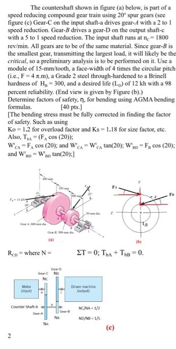
The countershaft shown in figure (a) below, is part of a speed reducing compound gear train using 20 spur gears (see figure (c) Gear-C

The countershaft shown in figure (a) below, is part of a speed reducing compound gear train using 20 spur gears (see figure (c) Gear-C on the input shaft-a drives gear-A with a 2 to 1 speed reduction. Gear-B drives a gear-D on the output shaft-c with a 5 to I speed reduction. The input shaft runs at ne= 1800 rev/min. All gears are to be of the same material. Since gear-B is the smallest gear, transmitting the largest load, it will likely be the critical, so a preliminary analysis is to be performed on it. Use a module of 15-mm/tooth, a face-width of 4 times the circular pitch (i.e., F= 4 a.m), a Grade 2 steel through-hardened to a Brinell hardness of H, = 300, and a desired life (L) of 12 kh with a 98 percent reliability. (End view is given by Figure (b).) Determine factors of safety, n, for bending using AGMA bending formulas. (The bending stress must be fully corrected in finding the factor of safety. Such as using Ko = 1.2 for overload factor and Ks = 1.18 for size factor, etc. Also, TA = (F, cos (20)): W'CA = F, cos (20); and W'CA = W'Ca tan(20); WRp = Fg cos (20); and W [40 pts.) "ap tan(20):] BD FA F-I N Ge dia (a) Rep = where N = ET = 0; TA + TB = 0. Gearo Ger-C No Nc Motor tinput) Driven machine toutput) Counter Shaft-b NC/NA - 1/2 Gear Gear-A Na ND/NB - 1/5 NA (c) 2
Step by Step Solution
★★★★★
3.52 Rating (159 Votes )
There are 3 Steps involved in it
Step: 1

Get Instant Access to Expert-Tailored Solutions
See step-by-step solutions with expert insights and AI powered tools for academic success
Step: 2

Step: 3

Ace Your Homework with AI
Get the answers you need in no time with our AI-driven, step-by-step assistance
Get Started


