Answered step by step
Verified Expert Solution
Question
1 Approved Answer
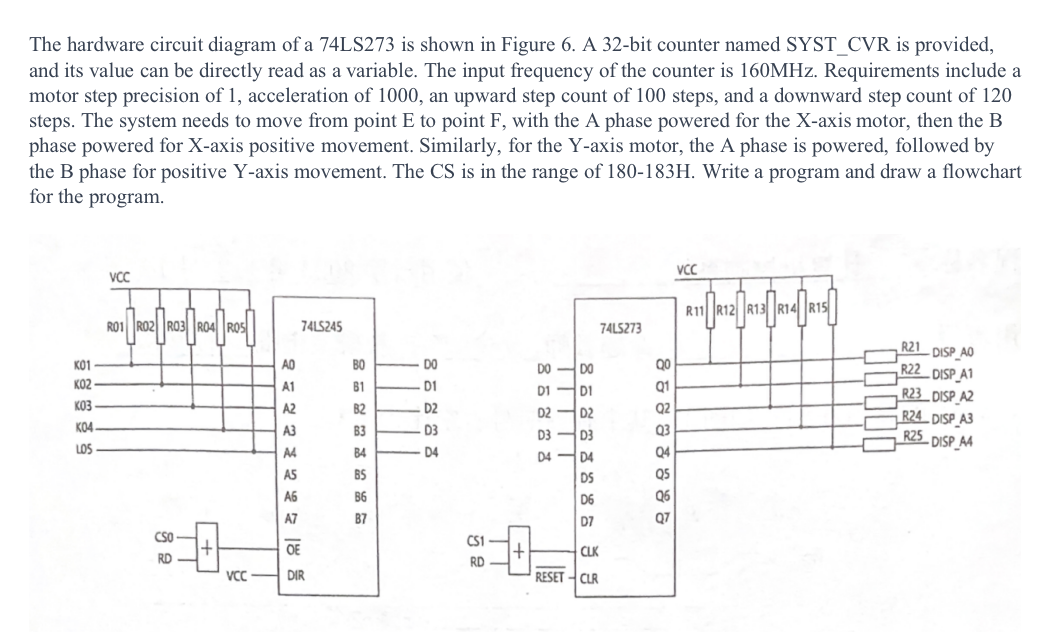
The hardware circuit diagram of a 7 4 LS 2 7 3 is shown in Figure 6 . A 3 2 - bit counter named
The hardware circuit diagram of a LS is shown in Figure A bit counter named SYSTCVR is provided,
and its value can be directly read as a variable. The input frequency of the counter is Requirements include a
motor step precision of acceleration of an upward step count of steps, and a downward step count of
steps. The system needs to move from point to point with the A phase powered for the axis motor, then the
phase powered for axis positive movement. Similarly, for the axis motor, the A phase is powered, followed by
the B phase for positive Yaxis movement. The CS is in the range of Write a program and draw a flowchart
for the program.

Step by Step Solution
There are 3 Steps involved in it
Step: 1

Get Instant Access to Expert-Tailored Solutions
See step-by-step solutions with expert insights and AI powered tools for academic success
Step: 2

Step: 3

Ace Your Homework with AI
Get the answers you need in no time with our AI-driven, step-by-step assistance
Get Started


