Question: The IEEE 14 Bus Test system, shown in Fig. I represents a portion of the American Electric Power System (in the Midwestern US) as of
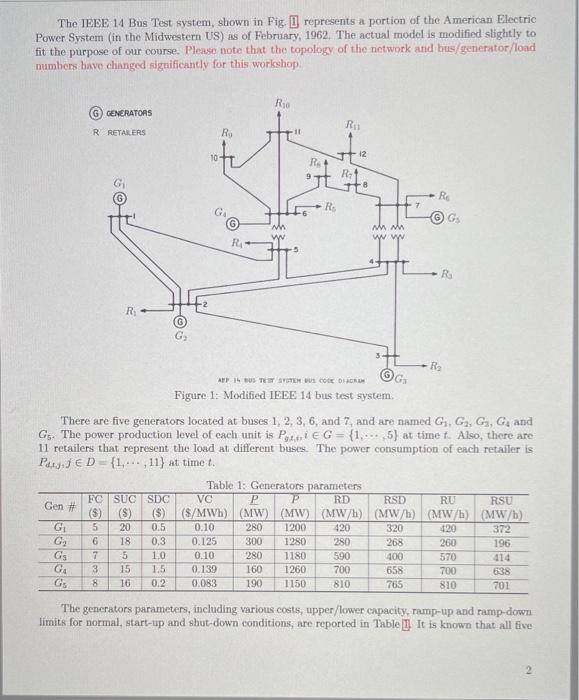
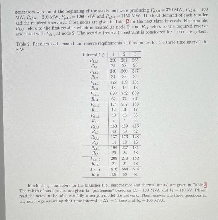
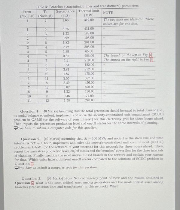
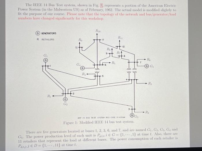
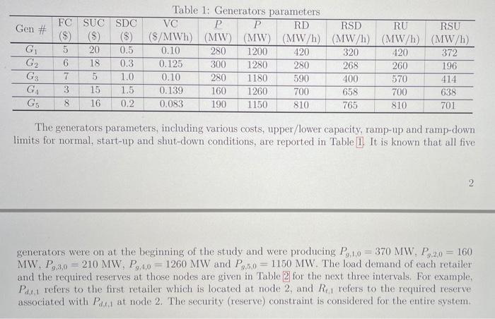
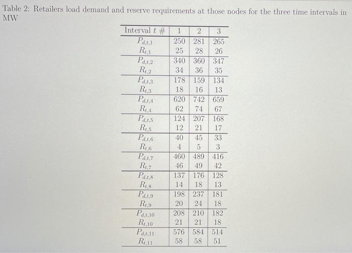

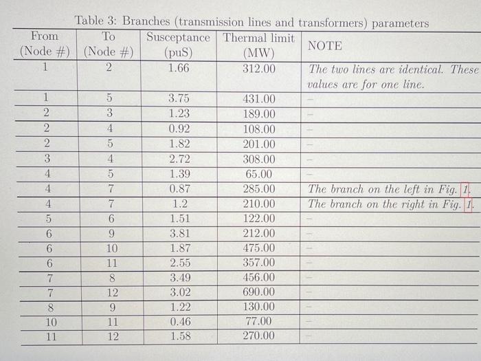
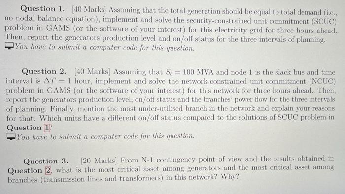
The IEEE 14 Bus Test system, shown in Fig. I represents a portion of the American Electric Power System (in the Midwestern US) as of February, 1962. The actual model is modified slightly to fit the purpose of our course. Please note that the topology of the network and bus/generator/load numbers have changed significantly for this workshop Rio GENERATORS RE RRETALERS R 11 10 12 RA + R RO RS 7 GG wh w Mhmh ww R 5 RS R 05 G R3 AT 4 BUS TEISTOTES CODE DER G Figure 1: Modified IEEE 14 bus test system. There are five generators located at buses 1, 2, 3, 6, and 7, and are named G. G, G, Gand Gs. The power production level of each unit is Pie G = {1,... 5) at time t. Also, there are 11 retailers that represent the load at different buses. The power consumption of each retailer is PUTED - {1,...,11) at time to Table 1: Generators parameters FC SUC SDC VC P P RD Gen RSD RU RSU (8) (8) (5) (S/MWh) (MW) (MW) (MWh) (MW/h) (MW/h) (MW/h) G 5 20 0.5 0.10 280 1200 420 320 420 372 G 6 18 0.3 0.125 300 1280 280 268 260 196 GS 7 1.0 0.10 280 1180 590 100 570 414 G4 3 15 1.5 0.139 160 1260 700 658 700 638 GS 8 16 0.2 0.083 190 1150 810 765 810 701 $ GON 00 & OP MC The generators parameters, including various costs, upper/lower capacity, ramp-up and ramp-down limits for normal, start-up and shut-down conditions, are reported in Table II It is known that all five generators were on at the beginning of the study and were producing P0.1,0 = 370 MW, P,2,0 = 160 MW, P9,3,0 = 210 MW, P4,0 = 1260 MW and P,5,0 1150 MW. The load demand of each retailer and the required reserves at those nodes are given in Table 2 for the next three intervals. For example, Pa,1,1 refers to the first retailer which is located at node 2, and Rc1 refers to the required reserve associated with P1 at node 2. The security (reserve) constraint is considered for the entire system. Table 2: Retailers load demand and reserve requirements at those nodes for the three time intervals in MW Intervalt # 2 3 250 281 265 25 28 26 340 360 347 34 36 35 178 159 134 18 16 13 620 742 659 62 74 67 124 207 168 12 21 17 40 45 33 4 5 3 460 489 416 46 49 42 137 176 128 14 18 13 198 237 181 R9 20 24 18 208 210 182 R10 21 21 18 576 584 514 R6,11 58 58 51 , 1 Rui Pata R.2 ,1,3 Rez Part Rea P4,15 RES Paco R6 Parr Rez P4.18 RS P4,9 Pagio Paru In addition, parameters for the branches (i.e., susceptance and thermal limits) are given in Table 3 The values of susceptance are given in "puSiemens" based on S6 = 100 MVA and V = 110 kV. Please read the notes in the table carefully when you model the network. Then, answer the three questions in the next page assuming that time interval is AT = 1 hour and Sb = 100 MVA. Table 3: Branches (transmission lines and transformers) parameters From To Susceptance Thermal limit NOTE (Node # (Node #) (pus) (MW) 1 2 1.66 312.00 The two lines are identical. These values are for one line. 1 5 3.75 431.00 2 3 1.23 189.00 2 4 0.92 108.00 2 5 1.82 201.00 3 4 2.72 308.00 4 5 1.39 65.00 4 7 0.87 285.00 The branch on the left in Fig. !! 4 7 1.2 210.00 The branch on the right in Fig. 5 6 1.51 122.00 6 9 3.81 212.00 6 10 1.87 475.00 6 11 2.55 357.00 7 8 3.49 456.00 7 12 3.02 690.00 8 9 1.22 130.00 10 11 0:46 77.00 11 12 1.58 270.00 Question 1. (40 Marks] Assuming that the total generation should be equal to total demand (1.c. no nodal balance equation), implement and solve the security-constrained unit commitment (SCUC) problem in GAMS (or the software of your interest) for this electricity grid for three hours ahead. Then, report the generators production level and on/off status for the three intervals of planning You have to submit a computer code for this question Question 2.40 Marks Assuming that Ss = 100 MVA and node 1 is the slack bus and time interval is AT = 1 hour, implement and solve the network-constrained unit commitment (NCUC) problem in GAMS (or the software of your interest) for this network for three hours ahead. Then, report the generators production level, on/off status and the branches' power flow for the three intervals of planning. Finally, mention the most under-utilised branch in the network and explain your reasons for that. Which units have a different on/off status compared to the solutions of SCUC problem in Question U You have to submit a computer code for this question. Question 3. [20 Marks) From N-1 contingency point of view and the results obtained in Question 2 what is the most critical asset among generators and the most critical asset among branches (transmission lines and transformers) in this network? Why? The IEEE 14 Bus Test system, shown in Fig. I represents a portion of the American Electric Power System (in the Midwestern US) as of February, 1962. The actual model is modified slightly to fit the purpose of our course. Please note that the topology of the network and bus/generator/load numbers have changed significantly for this workshop R, G GENERATORS R1 R RETAILERS Ro sti 10 12 RA 9 R R Rs G nh www WW R4 5 Rs -2 RO G G2 3 R APP IS BUS TEST SYSTEM HUS CODE DIAGRAM G Figure 1: Modified IEEE 14 bus test system There are five generators located at buses 1. 2. 3, 6, and 7 and are named G1, G2, G3, G, and Gs. The power production level of each unit is Potie G = {1,...,5) at time t. Also, there are 11 retailers that represent the load at different buses. The power consumption of each retailer is Puljuje D= {1,...,11} at timet Gen # A G G2 G: G G Table 1: Generators parameters FC SUC SDC VC P P RD RSD RU RSU ($) (5) (S/MWh) (MW) (MW) (MW/h) (MW/h) (MW/h) (MW/h) 5 20 0.5 0.10 280 1200 420 320 420 372 6 18 0.3 0.125 300 1280 280 268 260 196 7 5 1.0 0.10 280 1180 590 400 570 414 3 15 1.5 0.139 160 1260 700 658 700 638 8 16 0.2 0.083 190 1150 810 810 701 765 The generators parameters, including various costs, upper/lower capacity, ramp-up and ramp-down limits for normal, start-up and shut-down conditions, are reported in Table 1 It is known that all five MW, P3,0 generators were on at the beginning of the study and were producing P, 10 = 370 MW. P.2,0 = 160 210 MW, P.4,0 = 1260 MW and P.,6.0 = 1150 MW. The load demand of each retailer and the required reserves at those nodes are given in Table 2 for the next three intervals. For example, Pau refers to the first retailer which is located at node 2, and Rui refers to the required reserve associated with Paul at node 2. The security (reserve) constraint is considered for the entire system. Table 2: Retailers load demand and reserve requirements at those nodes for the three time intervals in MW Interval t # 1 2 3 250 281 265 25 28 26 340 360 347 34 36 35 178 159 134 18 16 13 620 742 659 62 74 67 124 207 168 12 21 17 40 45 33 4 5 3 460 489 416 46 49 42 137 176 128 14 18 13 198 237 181 20 24 18 208 210 182 21 21 18 576 581 514 58 58 51 Part.1 R1 P2.12 R: 2 Pd.13 R3 Pat, RU Par,5 RS Pato RO Paar Rez Pats Rus Pang RO Pa, 10 Rio Patil R11 In addition, parameters for the branches (i.e., susceptance and thermal limits) are given in Table 3. The values of susceptance are given in "puSiemens" based on So = 100 MVA and Vi= 110 kV. Please read the notes in the table carefully when you model the network. Then, answer the three questions in the next page assuming that time interval is AT = 1 hour and S) = 100 MVA. Table 3: Branches (transmission lines and transformers) parameters From Susceptance Thermal limit NOTE (Node #) (Node #) (pus) (MW) 1 2 1.66 312.00 The two lines are identical. These values are for one line. 1 5 3.75 431.00 2 3 1.23 189.00 2 4 0.92 108.00 2 5 1.82 201.00 3 4 2.72 308.00 4 5 1.39 65.00 4. 7 0.87 285.00 The branch on the left in Fig. 1. 4 7 1.2 210.00 The branch on the right in Fig. 1. 5 6 1.51 122.00 6 9 3.81 212.00 6 10 1.87 475.00 6 11 2.55 357.00 7 8 3.49 456.00 7 12 3.02 690.00 8 9 1.22 130.00 10 11 0.46 77.00 11 12 1.58 270.00 Question 1. [40 Marks) Assuming that the total generation should be equal to total demand (i.e. no nodal balance equation), implement and solve the security-constrained unit commitment (SCUC) problem in GAMS (or the software of your interest) for this electricity grid for three hours ahead. Then, report the generators production level and on/off status for the three intervals of planning, You have to submit a computer code for this question. Question 2. [40 Marks) Assuming that Si = 100 MVA and node 1 is the slack bus and time interval is AT 1 hour, implement and solve the network-constrained unit commitment (NCUC) problem in GAMS (or the software of your interest) for this network for three hours ahead. Then, report the generators production level, on/off status and the branches power flow for the three intervals of planning. Finally, mention the most under-utilised branch in the network and explain your reasons for that. Which uits have a different on/off status compared to the solutions of SCUC problem in Question 1? You have to submit a computer code for this question. a Question 3 [20 Marks] From N-1 contingency point of view and the results obtained in Question 2. what is the most critical asset among generators and the most critical asset among branches (transmission lines and transformers) in this network? Why
Step by Step Solution
There are 3 Steps involved in it

Get step-by-step solutions from verified subject matter experts


