Answered step by step
Verified Expert Solution
Question
1 Approved Answer
The inlet of a centrifugal water pump is 2.3 m above the free surface from which it draws. The inlet consists of 4 m


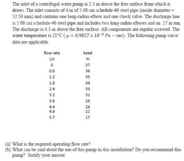
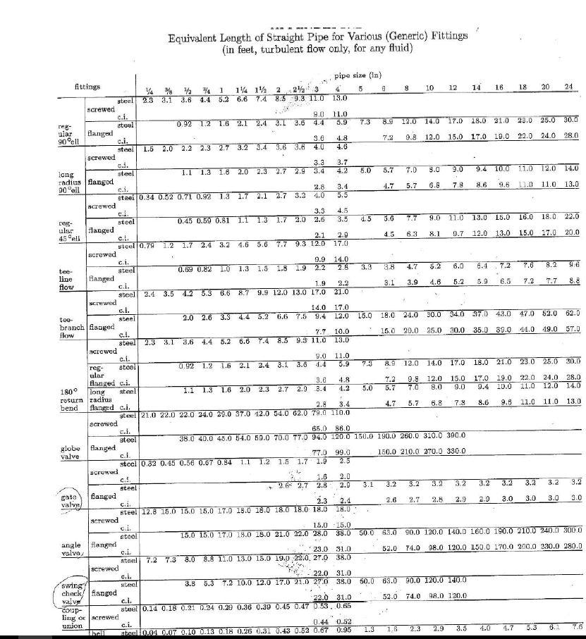
The inlet of a centrifugal water pump is 2.3 m above the free surface from which it draws. The inlet consists of 4 m of 5.08 cm schedule-40 steel pipe (inside diameter = 52.50 mm) and contains one long-radius elbow and one check valve. The discharge line is 5 08 cm schedule-40 steel pipe and includes two long-radius elbows and an 27 m nun. The discharge is 6.3 m above the free surface. All components are regular screwed. The water temperature is 21C (u = 0.9827 x 1o- Pa sec). The following pump curve data are applicable. flow rate head L/s m 37 0.6 36 1.2 35 1.8 34 2.4 33 3.2 31 3.6 29 4.4 26 4.8 22 5.7 17 (a) What is the required operating flow rate? (b) What can be said about the use of this pump in this installation? Do you recommend this pump? Justify your answer. Equivalent Length of Straight Pipe for Various (Generic) Fittings (in feet, turbulent flow only, for any fluid) pipe size (in) fittings 10 12 14 16 18 20 24 14 1% 2 4.4 5.2 6.6 7.4 85 9.3 11.0 13.0 22 3 steel 2.3 3.1 3.6 screwed c.i. eteel langed ci. steel screwed cd. 9.0 11.0 5.9 12.0 14.0 17.0 18.0 21.0 23.0 25.0 30.0 0.92 1.2 1.6 2.1 2.4 3.1 3.6 4.4 7.3 8.9 reg- alar 90ell 3.0 9.8 12.0 15.0 17.0 19.0 22.0 24.0 28.0 4.8 4.6 7.2 1.5 2.0 2.2 2.3 2.7 3.2 3.4 3.6 3.6 4.0 3.7 3.3 2.7 2.9 3.4 11.0 1.3 1.6 2.0 2.3 4.2 5.0 5.7 7.0 3.0 9.0 9.4 10.0 12.0 14.0 steel 1.1 long radius flanged 90 ell 2.8 4.7 5.7 6.8 7.8 8.6 9.6 11.0 11.0 13.0 3.4 5.5 c.i. steel 0.34 0.52 0.71 0.92 1.3 1.7 2.1 2.7 3.2 4.0 acrewed ci. steel langed c.t. 3.3 2.6 4.5 3.5 4.5 3.6 7.7 9.0 11.0 13.0 15.0 16.0 18.0 22.0 0.45 0.59 0.81 1.1 1.3 1.7 2.0 reg- ular 6.3 9.7 12.0 13.0 15.0 17.0 20.0 8.1 2.9 17.0 4.5 2.1 1.2 1.7 2.4 3.2 4.6 5.6 7.7 9.3 12.0 45 eli steel 0.79 scrowed 9.9 2.2 14.0 2.8 c.i. 4.7 5.2 6.0 6.4 7.2 7.6 8.2 9.6 0.69 0.82 1.0 1.3 1.5 1.8 1.9 3.3 3.8 steel fianged c.i. steel screwed c.i. steel branch Hanged c.i. tee- line flow 3.1 3.9 4.6 5.2 5.9 6.5 7.2 T.7 8.8 2.2 21.0 1.9 2.4 3.5 4.2 5.3 6.6 8.7 9.9 12.0 13.0 17.0 14.0 17.0 15.0 18.0 24.0 30.0 34.0 37.0 43.0 47.0 62.0 62.0 2.0 2.6 3.3 4.4 5.2 6.6 7.5 9.4 12.0 tee- 15.0 20.0 25.0 30.0 35.0 39.0 44.0 49.0 57.0 7.7 10.0 13.0 flow steel 2.3 3.1 3.6 4.4 5.2 6.6 7.4 8.5 9.3 11.0 acrewed c.i. 11.0 5.9 9.0 2.4 3.1 3.6 7.3 8.9 12.0 14.0 17.0 18.0 21.0 23.0 25.0 30.0 steel 0.92 1.2 1.6 2.1 4.4 reg- ular flanged c.i. long rosurn radius flanged c.i. 7.2 5.7 9.8 7.0 12.0 8.0 15.0 9.0 17.0 9.4 19.0 22.0 24.0 28.0 10.0 3.8 4.8 4.2 11.0 12.0 14.0 180 steel 1.1 1.3 1.6 2.0 2.3 2.7 2.9 3.4 5.0 5.7 6.8 7.8 8.6 9.8 11.0 11.0 13.0 2.8 steel 21.0 22.0 22.0 24.0 29.0 37.0 42.0 54.0 62.0 79.0 110.0 3.4 4.7 bend scrowed c.i. 65.0 86.0 38.0 40.0 45.0 54.0 50.0 70.0 77.0 94.0 120.0 150.0 190.0 260.0 310.0 300.0 steel globe langed valve 150.0 210.0 270.0 330.0 77.0 99.0 2.5 c. stcel 0.32 0.45 0.56 0.67 0.84 1.1 1.2 1.5 1.7 1.0 screwed c.! 1.6 2.8 2.0 2.9 2.6 2.7 3.1 3.2 3.2 3.2 3.2 3.2 3.2 3.2 3.2 3.2 steel gato flangud 3.0 2.1 2.8 2.9 2.9 3.0 3.0 3.0 valve c.i. steel 12.8 15.0 16.0 15.0 17.0 18.0 18.0 18.0 18.0 18.0 18.0 2.3 2.6 2.7 screwed c.i. etel 15.0 15.0 15.0 13.0 17.0 18.0 18.0 21.0 22.0 28.0 38.0 50.0 63.0 90.0 120.0 140.0 160.0 190.0 210.O 240.0 3000 angle valvo, Hanged c.i. steel screwed c.i. steel 23.0 31.0 74.0 98.0 120.0 L50.0 170.0 200.0 230.0 280.0 52.0 7.2 7.3 8.0 8.8 11.0 13.0 15.0 19.0 22.0, 27.0 38.0 22.0 31.0 3.8 5.3 T.2 10.0 12.0 17.0 21.0 27:0 38.0 50.0 63.0 90,0 120.0 140.0 swing check flanged valve oup- ling or screwed union 22.0 31.0 52.0 74.0 98.0 120.0 c.i. steel 0.14 0.18 0.21 0.24 0.20 0.36 0.39 0.45 0.47 D.33, 0.65 0.44 0.52 c.i. 1.3 1.6 2.9 3.5 4.0 4.7 5.3 7.6 2.3 steel0.04 0.07 0.10 0.13 0.18 0.26 0.31 0.43 0.52 0.67 0:95
Step by Step Solution
★★★★★
3.48 Rating (164 Votes )
There are 3 Steps involved in it
Step: 1
Calculation of friction factor We plot the system resistance curve by plotting 4 points in system re...
Get Instant Access to Expert-Tailored Solutions
See step-by-step solutions with expert insights and AI powered tools for academic success
Step: 2

Step: 3

Ace Your Homework with AI
Get the answers you need in no time with our AI-driven, step-by-step assistance
Get Started


