Answered step by step
Verified Expert Solution
Question
1 Approved Answer
The L -shaped cantilever beam, shown in Figure 4, is rigidly supported at its left end, point A, and subject to a downward force

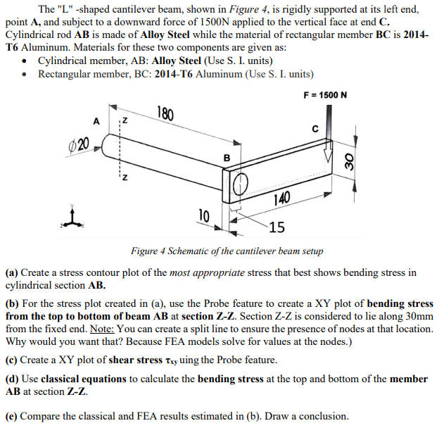
The "L" -shaped cantilever beam, shown in Figure 4, is rigidly supported at its left end, point A, and subject to a downward force of 1500N applied to the vertical face at end C. Cylindrical rod AB is made of Alloy Steel while the material of rectangular member BC is 2014- T6 Aluminum. Materials for these two components are given as: Cylindrical member, AB: Alloy Steel (Use S. I. units) Rectangular member, BC: 2014-T6 Aluminum (Use S. I. units) 180 020 B 140 F = 1500 N 30 10 15 Figure 4 Schematic of the cantilever beam setup (a) Create a stress contour plot of the most appropriate stress that best shows bending stress in cylindrical section AB. (b) For the stress plot created in (a), use the Probe feature to create a XY plot of bending stress from the top to bottom of beam AB at section Z-Z. Section Z-Z is considered to lie along 30mm from the fixed end. Note: You can create a split line to ensure the presence of nodes at that location. Why would you want that? Because FEA models solve for values at the nodes.) (c) Create a XY plot of shear stress Txy uing the Probe feature. (d) Use classical equations to calculate the bending stress at the top and bottom of the member AB at section Z-Z. (e) Compare the classical and FEA results estimated in (b). Draw a conclusion.
Step by Step Solution
There are 3 Steps involved in it
Step: 1

Get Instant Access to Expert-Tailored Solutions
See step-by-step solutions with expert insights and AI powered tools for academic success
Step: 2

Step: 3

Ace Your Homework with AI
Get the answers you need in no time with our AI-driven, step-by-step assistance
Get Started


