Question
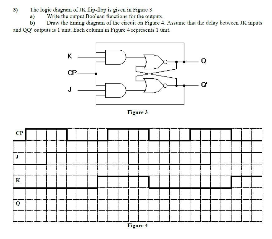
The logic diagram of JK flip-flop is given in Figure 3. ) b) 3) Write the output Boolean functions for the outputs. Draw the
The logic diagram of JK flip-flop is given in Figure 3. ) b) 3) Write the output Boolean functions for the outputs. Draw the timing diagram of the circuit on Figure 4. Assume that the delay between JK inputs and QQ' outputs is 1 unit. Each column in Figure 4 represents 1 unit. K CP. Q' J Figure 3 J K Q Figure 4
Step by Step Solution
3.51 Rating (148 Votes )
There are 3 Steps involved in it
Step: 1
The truth table is aThus ...
Get Instant Access to Expert-Tailored Solutions
See step-by-step solutions with expert insights and AI powered tools for academic success
Step: 2

Step: 3

Ace Your Homework with AI
Get the answers you need in no time with our AI-driven, step-by-step assistance
Get StartedRecommended Textbook for
Physical Chemistry
Authors: Thomas Engel, Philip Reid
3rd edition
805338423, 080533842X, 978-0321812001
Students also viewed these Electrical Engineering questions
Question
Answered: 1 week ago
Question
Answered: 1 week ago
Question
Answered: 1 week ago
Question
Answered: 1 week ago
Question
Answered: 1 week ago
Question
Answered: 1 week ago
Question
Answered: 1 week ago
Question
Answered: 1 week ago
Question
Answered: 1 week ago
Question
Answered: 1 week ago
Question
Answered: 1 week ago
Question
Answered: 1 week ago
Question
Answered: 1 week ago
Question
Answered: 1 week ago
Question
Answered: 1 week ago
Question
Answered: 1 week ago
Question
Answered: 1 week ago
Question
Answered: 1 week ago
Question
Answered: 1 week ago
Question
Answered: 1 week ago
Question
Answered: 1 week ago
Question
Answered: 1 week ago
View Answer in SolutionInn App


