Answered step by step
Verified Expert Solution
Question
1 Approved Answer
The next generation classroom door model that can be used during the Covid-19 pandemic period is shown below. In this system, the student coming to


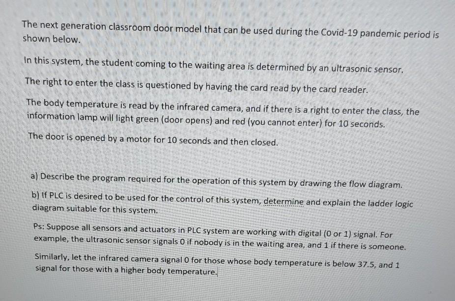
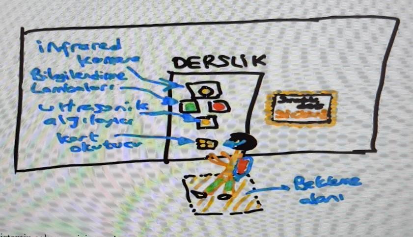
The next generation classroom door model that can be used during the Covid-19 pandemic period is shown below. In this system, the student coming to the waiting area is determined by an ultrasonic sensor. The right to enter the class is questioned by having the card read by the card reader. The body temperature is read by the infrared camera, and if there is a right to enter the class, the information lamp will light green (door opens) and red (you cannot enter) for 10 seconds. The door is opened by a motor for 10 seconds and then closed. a) Describe the program required for the operation of this system by drawing the flow diagram. b) If PLC is desired to be used for the control of this system, determine and explain the ladder logic diagram suitable for this system. Ps: Suppose all sensors and actuators in PLC system are working with digital (0 or 1) signal. For example, the ultrasonic sensor signals o if nobody is in the waiting area, and 1 if there is someone. Similarly, let the infrared camera signal O for those whose body temperature is below 37.5, and 1 signal for those with a higher body temperature. infrared Komare Bilgilendiare Lamlenlere Utesnik algeloster DERSUIK 0 B ollu tuo Bekelere bo The next generation classroom door model that can be used during the Covid-19 pandemic period is shown below. In this system, the student coming to the waiting area is determined by an ultrasonic sensor. The right to enter the class is questioned by having the card read by the card reader. The body temperature is read by the infrared camera, and if there is a right to enter the class, the information lamp will light green (door opens) and red (you cannot enter) for 10 seconds. The door is opened by a motor for 10 seconds and then closed. a) Describe the program required for the operation of this system by drawing the flow diagram. b) If PLC is desired to be used for the control of this system, determine and explain the ladder logic diagram suitable for this system. Ps: Suppose all sensors and actuators in PLC system are working with digital (0 or 1) signal. For example, the ultrasonic sensor signals o if nobody is in the waiting area, and 1 if there is someone. Similarly, let the infrared camera signal O for those whose body temperature is below 37.5, and 1 signal for those with a higher body temperature. infrared Komare Bilgilendiare Lamlenlere Utesnik algeloster DERSUIK 0 B ollu tuo Bekelere bo
Step by Step Solution
There are 3 Steps involved in it
Step: 1

Get Instant Access to Expert-Tailored Solutions
See step-by-step solutions with expert insights and AI powered tools for academic success
Step: 2

Step: 3

Ace Your Homework with AI
Get the answers you need in no time with our AI-driven, step-by-step assistance
Get Started


