Question
The no-load voltage in the voltage-divider circuit shown in the figure is 8 V . The smallest load resistor that is ever connected to the
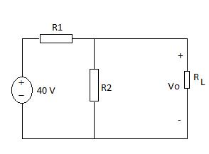
The no-load voltage in the voltage-divider circuit shown in the figure is 8 V . The smallest load resistor that is ever connected to the divider is 3.5 k? When the divider is loaded, vo is not to drop below 7.5 V . (Figure 1)
a. Design the divider circuit to meet the specifications just mentioned. Specify the numerical values of R1 and R2.
b. Assume the power ratings of the commercially available resistors are 1/16, 1/8, 1/4, 1, and 2 W. What power rating would you specify?

R1 R Vo 40 V R2 +
Step by Step Solution
3.46 Rating (156 Votes )
There are 3 Steps involved in it
Step: 1

Get Instant Access to Expert-Tailored Solutions
See step-by-step solutions with expert insights and AI powered tools for academic success
Step: 2

Step: 3

Ace Your Homework with AI
Get the answers you need in no time with our AI-driven, step-by-step assistance
Get StartedRecommended Textbook for
Fundamentals of Physics
Authors: Jearl Walker, Halliday Resnick
8th Extended edition
471758019, 978-0471758013
Students also viewed these Electrical Engineering questions
Question
Answered: 1 week ago
Question
Answered: 1 week ago
Question
Answered: 1 week ago
Question
Answered: 1 week ago
Question
Answered: 1 week ago
Question
Answered: 1 week ago
Question
Answered: 1 week ago
Question
Answered: 1 week ago
Question
Answered: 1 week ago
Question
Answered: 1 week ago
Question
Answered: 1 week ago
Question
Answered: 1 week ago
Question
Answered: 1 week ago
Question
Answered: 1 week ago
Question
Answered: 1 week ago
Question
Answered: 1 week ago
Question
Answered: 1 week ago
Question
Answered: 1 week ago
Question
Answered: 1 week ago
Question
Answered: 1 week ago
Question
Answered: 1 week ago
Question
Answered: 1 week ago
View Answer in SolutionInn App


