Answered step by step
Verified Expert Solution
Question
1 Approved Answer
The objective of this project is to develop a mathematical model for a vehicle, simulate the response of the vehicle to the engine being


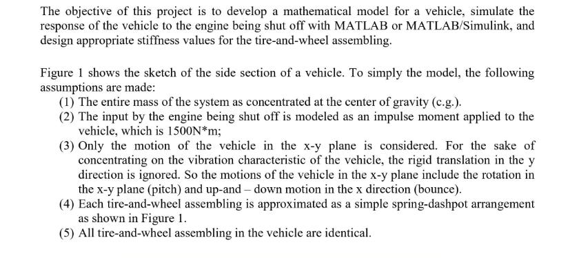
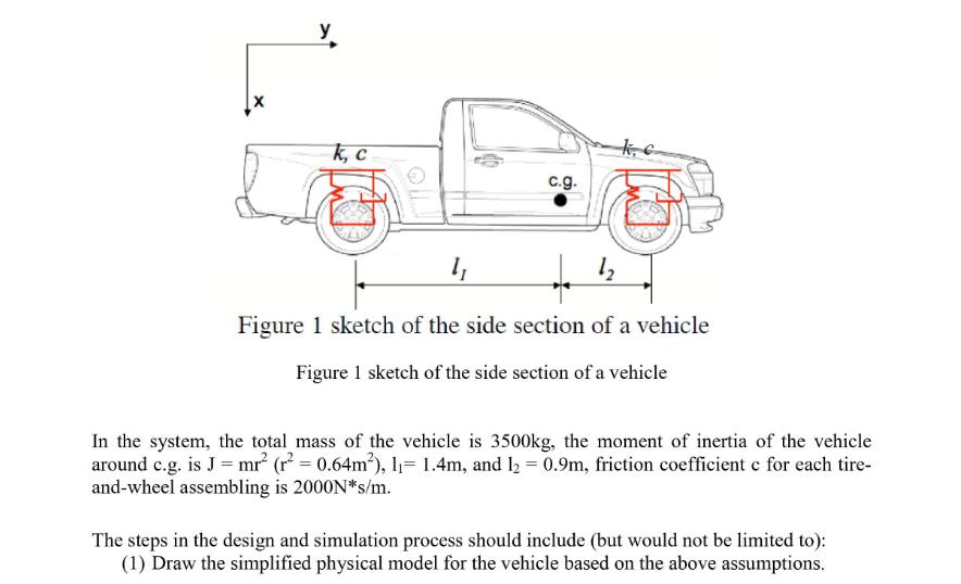
The objective of this project is to develop a mathematical model for a vehicle, simulate the response of the vehicle to the engine being shut off with MATLAB or MATLAB/Simulink, and design appropriate stiffness values for the tire-and-wheel assembling. Figure 1 shows the sketch of the side section of a vehicle. To simply the model, the following assumptions are made: (1) The entire mass of the system as concentrated at the center of gravity (c.g.). (2) The input by the engine being shut off is modeled as an impulse moment applied to the vehicle, which is 1500N*m; (3) Only the motion of the vehicle in the x-y plane is considered. For the sake of concentrating on the vibration characteristic of the vehicle, the rigid translation in the y direction is ignored. So the motions of the vehicle in the x-y plane include the rotation in the x-y plane (pitch) and up-and-down motion in the x direction (bounce). (4) Each tire-and-wheel assembling is approximated as a simple spring-dashpot arrangement as shown in Figure 1. (5) All tire-and-wheel assembling in the vehicle are identical. k, c c.g. 1 12 Figure 1 sketch of the side section of a vehicle Figure 1 sketch of the side section of a vehicle In the system, the total mass of the vehicle is 3500kg, the moment of inertia of the vehicle around c.g. is J = mr (r = 0.64m), l= 1.4m, and l = 0.9m, friction coefficient c for each tire- and-wheel assembling is 2000N*s/m. The steps in the design and simulation process should include (but would not be limited to): (1) Draw the simplified physical model for the vehicle based on the above assumptions.
Step by Step Solution
★★★★★
3.31 Rating (160 Votes )
There are 3 Steps involved in it
Step: 1
The skin friction coefficient Cf for a laminar boundary ...
Get Instant Access to Expert-Tailored Solutions
See step-by-step solutions with expert insights and AI powered tools for academic success
Step: 2

Step: 3

Ace Your Homework with AI
Get the answers you need in no time with our AI-driven, step-by-step assistance
Get Started


