Answered step by step
Verified Expert Solution
Question
1 Approved Answer
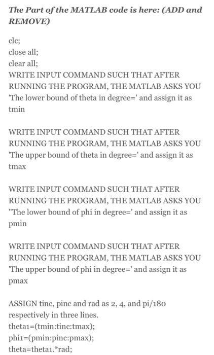
The Part of the MATLAB code is here: (ADD and REMOVE) clc; close all; clear all; WRITE INPUT COMMAND SUCH THAT AFTER RUNNING THE

![theta-thetai.*rad; phi=phis. rad; USE meshgrid command such that [THETA, PHI] is meshgrid of (theta, phi);](https://dsd5zvtm8ll6.cloudfront.net/si.experts.images/answers/2023/10/651f1a23e758e_123651f1a23e3783.jpg)

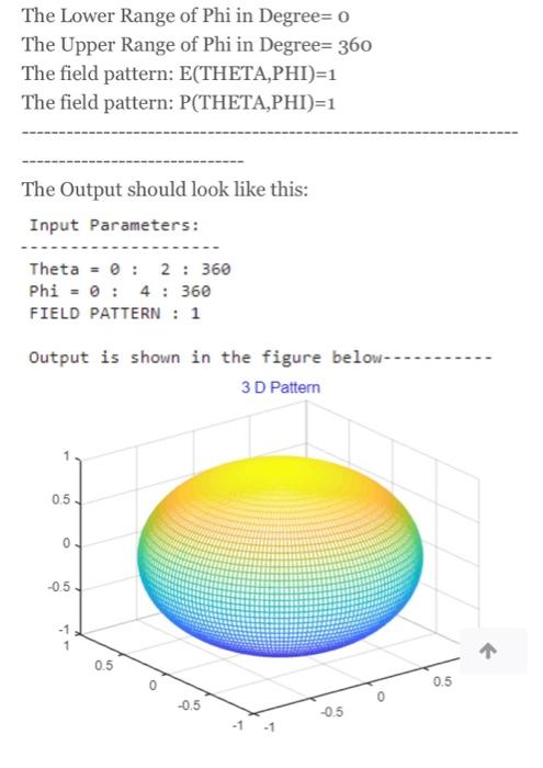
The Part of the MATLAB code is here: (ADD and REMOVE) clc; close all; clear all; WRITE INPUT COMMAND SUCH THAT AFTER RUNNING THE PROGRAM, THE MATLAB ASKS YOU "The lower bound of theta in degree=' and assign it as tmin WRITE INPUT COMMAND SUCH THAT AFTER RUNNING THE PROGRAM, THE MATLAB ASKS YOU "The upper bound of theta in degree=' and assign it as tmax WRITE INPUT COMMAND SUCH THAT AFTER RUNNING THE PROGRAM, THE MATLAB ASKS YOU "The lower bound of phi in degree=' and assign it as pmin WRITE INPUT COMMAND SUCH THAT AFTER RUNNING THE PROGRAM, THE MATLAB ASKS YOU "The upper bound of phi in degree=' and assign it as pmax ASSIGN tinc, pine and rad as 2, 4, and pi/180 respectively in three lines. theta1=(tmin:tine:tmax); phil (pmin:pinc:pmax); theta=theta1.*rad; theta=theta1.*rad; phi-phil.*rad; USE meshgrid command such that [THETA, PHI] is meshgrid of (theta, phi); y1=input("The field pattern: E(THETA,PHI)='); v=input('The field pattern: P(THETA,PHI)=','s'); NOW ASSIGN Y AS ABSOLUTE VALUE OF y1 ratio=max(max(y)); PHI,y); %learn about [X,Y,Z]=sph2cart(THETA, sph2cart command mesh(X,Y,Z); % also learn mesh command title('3 D Pattern', 'Color', 'b', 'FontName','Helvetica','FontSize', 12, Font fprintf(" Input Parameters: ----------- -)); fprintf(" Theta =%2.of,tmin); fprintf(': %2.of,tinc); fprintf(': %2.of, tmax); fprintf(" Phi=%2.0f,pmin); fprintf('%2.of,pinc); fprintf(: %2.of,pmax); fprintf(" FIELD PATTERN: %s',v) fprintf(' Output is shown in the figure below-------- fprintf(" '); after running give the following parameters: The Lower Range of Theta in Degree= o The Upper Range of Theta in Degree= 360 The Lower Range of Phi in Degree o The Lower Range of Phi in Degree o The Upper Range of Phi in Degree= 360 The field pattern: E(THETA,PHI)=1 The field pattern: P(THETA,PHI)=1 The Output should look like this: Input Parameters: Theta = 0 : 2:360 Phi = 0 4 : 360 FIELD PATTERN : 1 Output is shown in the figure below-- 3D Pattern 0.5 0 -0.5 0.5 -0.5 -1 -0.5 O 0.5 The Part of the MATLAB code is here: (ADD and REMOVE) clc; close all; clear all; WRITE INPUT COMMAND SUCH THAT AFTER RUNNING THE PROGRAM, THE MATLAB ASKS YOU "The lower bound of theta in degree=' and assign it as tmin WRITE INPUT COMMAND SUCH THAT AFTER RUNNING THE PROGRAM, THE MATLAB ASKS YOU "The upper bound of theta in degree=' and assign it as tmax WRITE INPUT COMMAND SUCH THAT AFTER RUNNING THE PROGRAM, THE MATLAB ASKS YOU "The lower bound of phi in degree=' and assign it as pmin WRITE INPUT COMMAND SUCH THAT AFTER RUNNING THE PROGRAM, THE MATLAB ASKS YOU "The upper bound of phi in degree=' and assign it as pmax ASSIGN tinc, pinc and rad as 2, 4, and pi/180 respectively in three lines. theta1=(tmin:tine:tmax); phil (pmin:pinc:pmax); theta=theta1.*rad; theta-thetai.*rad; phi-phii. *rad; USE meshgrid command such that [THETA, PHI] is meshgrid of (theta,phi); y-input('The field pattern: E(THETA, PHI)='); v=input('The field pattern: P(THETA,PHI)=','s'); NOW ASSIGN Y AS ABSOLUTE VALUE OF y1 ratio=max(max(y)); PHI,y); %learn about [X,Y,Z]=sph2cart(THETA, sph2cart command mesh(X,Y,Z); % also learn mesh command title('3 D Pattern', 'Color', 'b', 'FontName','Helvetica', 'FontSize', 12, Font fprintf(" Input Parameters: ----------- -)); fprintf(" Theta =%2.of,tmin); fprintf(': %2.of,tinc); fprintf(: %2.of, tmax); fprintf(" Phi=%2.0f,pmin); fprintf('%2.of,pinc); fprintf(': %2.of,pmax); fprintf(" FIELD PATTERN: %s',v) fprintf(" Output is shown in the figure below-------- fprintf(" '); after running give the following parameters: The Lower Range of Theta in Degree= o The Upper Range of Theta in Degree= 360 The Lower Range of Phi in Degree o The Lower Range of Phi in Degree- o The Upper Range of Phi in Degree= 360 The field pattern: E(THETA,PHI)=1 The field pattern: P(THETA,PHI)=1 The Output should look like this: Input Parameters: Theta = 0 : 2:360 Phi = 0 : 4 : 360 FIELD PATTERN : 1 Output is shown in the figure below-- 3D Pattern 0.5 0 -0.5 0.5 -0.5 -1 -0.5 O 0.5
Step by Step Solution
There are 3 Steps involved in it
Step: 1
The images youve provided describe a series of instructions for writing MATLAB code to generate a 3D plot The instructions provide details on how to s...
Get Instant Access to Expert-Tailored Solutions
See step-by-step solutions with expert insights and AI powered tools for academic success
Step: 2

Step: 3

Ace Your Homework with AI
Get the answers you need in no time with our AI-driven, step-by-step assistance
Get Started


