Question
a) A hydraulic cylinder with a bore of 120mm and a piston rod diameter of 80mm is operated at a hydraulic pressure of 100 bar
a) A hydraulic cylinder with a bore of 120mm and a piston rod diameter of 80mm is operated at a hydraulic pressure of 100 bar and is required to extend at a speed of 1m/s. Calculate the following:
i. The required flow rate in LPM of oil to extend the cylinder.
ii. The load carried by the cylinder during extension.
iii. The power exerted by the cylinder during extension.
iv. Assuming that the flow rate in (i) is applied to the annulus side of the cylinder, calculate the retraction speed.
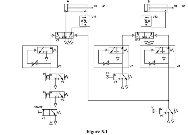
b) The pneumatic system shown in Figure 3.1 below is used to drive two double acting cylinders A and B. 
i. Analyze the circuit and explain the expected cylinder sequence behavior when the Start lever is pressed.
ii. Describe the functionalities of valve arrangements V6, V7 and V8. Explain how they affect the motions of cylinders A and B?
iii. Explain the cylinder circuit behavior when V6, V7 and V8 are removed.
iv. Describe the functionalities of valves V11 and V12. Explain how they affect the motions of cylinders A and B?
v. Determine the cylinder final positions when the Start lever is deactivated
c). Design and draw a pneumatic circuit one unit of 3/2 way valve, one unit of flow control valve and one unit of single acting cylinder with spring return that performs the following operations:
• The cylinder shall extend when a hand operated push button is pressed and remains pressed.
• When the push button is released, the cylinder shall retract.
• The cylinder shall retract at reduced speed and shall extend at normal speed. Choose the type of the flow control valve that satisfy this requirement and include it in the circuit.
• Include the actuation methods for both ends of the 3/2 way valve.
• Assume that the pressure supply and release are available.
a0 a1 b0 b1 11 V12 V9 VAV V10 VAV V6 V7 V8 b0 a1 V3 V4 AV a0 V2 START b1 V1 V5 Figure 3.1
Step by Step Solution
3.30 Rating (156 Votes )
There are 3 Steps involved in it
Step: 1

Get Instant Access to Expert-Tailored Solutions
See step-by-step solutions with expert insights and AI powered tools for academic success
Step: 2

Step: 3

Ace Your Homework with AI
Get the answers you need in no time with our AI-driven, step-by-step assistance
Get Started


