

Question
The Question is about using C to Control multiple buttons and LEDs on a MSP432 microcontroller STARTER CODE: // This application uses button 1 and
The Question is about using C to Control multiple buttons and LEDs on a MSP432 microcontroller

STARTER CODE:
// This application uses button 1 and LED 1 // The operation is such that if you press the left button, as long as you keep the button pressed, // the LED is on. As soon as you release the button, LED is off and stays off until the button is pressed again. // This example use memory-mapped registers to communicate with GPIO peripherals. // This example also uses HAL functions to hide away details from the main function
#include
// According to the schematics on page 37 of the Launchpad user guide, // left button (button 1) is connected to pin 1 (bit1) #define LEFT_BUTTON BIT1
// According to the schematics on page 37 of the Launchpad user guide, // left LED (LED 1) is connected to pin 0 (bit0) #define LEFT_LED BIT0
// According to the schematics on page 37 of the Launchpad user guide, // When a button is pressed, it is grounded (logic 0) #define PRESSED 0
// This function initializes all the peripherals void initialize();
void TurnOn_Launchpad_LED1(); void TurnOff_Launchpad_LED1(); char SwitchStatus_Launchpad_Button1();
int main(void) {
initialize(); while (1) {
// If the button is not pressed, keep the LED off if (SwitchStatus_Launchpad_Button1() != PRESSED) TurnOff_Launchpad_LED1(); else TurnOn_Launchpad_LED1();
} }
void initialize() {
// step 1: Stop watchdog timer // We do this at the beginning of all our programs for now.Later we learn more about it. WDT_A_hold(WDT_A_BASE);
// step 2: Initializing LED1 // According to table 12.1 on page 678 of MSP432 User guide, // to create an output, all you need is to write a 1 to PxDIR for the specific bit you want // A common mistake is to write P1DIR = LEFT_LED instead of P1DIR |= LEFT_LED; P1DIR |= LEFT_LED; // Same as P1DIR = P1DIR | LEFT_LED;
// step 3: Initializing S1 (switch 1 or button 1) // According to the table on page 678 of MSP432 User guide, // to create an input with pull-up resistor, you need to do three things
// step 3.1: write a 0 to PxDIR for the specific bit you want P1DIR &= ~LEFT_BUTTON;
// step 3.2: write a 1 to PxREB for the specific bit you want P1REN |= LEFT_BUTTON;
// step 3.3: write a 1 to PxOUT for the specific bit you want P1OUT |= LEFT_BUTTON; // select pull-up }
void TurnOn_Launchpad_LED1() { //GPIO_setOutputHighOnPin(GPIO_PORT_P1, GPIO_PIN0); P1OUT = P1OUT | LEFT_LED; }
void TurnOff_Launchpad_LED1() { //GPIO_setOutputLowOnPin(GPIO_PORT_P1, GPIO_PIN0); P1OUT = P1OUT & ~LEFT_LED; }
char SwitchStatus_Launchpad_Button1() { //return (GPIO_getInputPinValue(GPIO_PORT_P1, GPIO_PIN1)); return (P1IN & LEFT_BUTTON); }
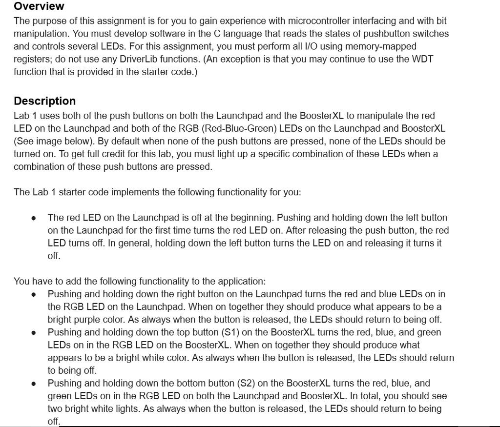
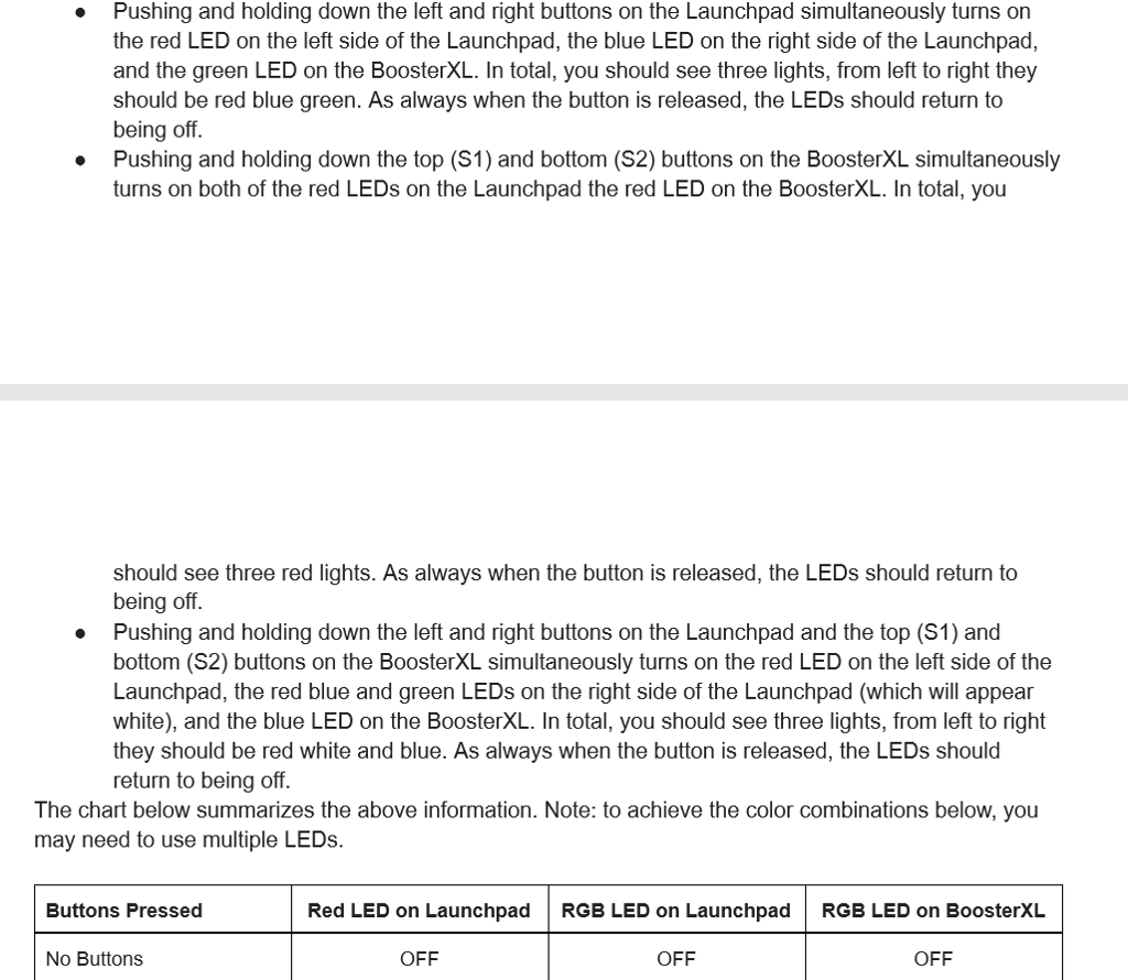
Overview The purpose of this assignment is for you to gain experience with microcontroller interfacing and with bit manipulation. You must develop software in the C language that reads the states of pushbutton switches and controls several LEDs. For this assignment, you must perform all l/O using memory-mapped registers; do not use any DriverLib functions. (An exception is that you may continue to use the WDT function that is provided in the starter code.) Description Lab 1 uses both of the push buttons on both the Launchpad and the BoosterXL to manipulate the red LED on the Launchpad and both of the RGB (Red-Blue-Green) LEDs on the Launchpad and BoosterXL (See image below). By default when none of the push buttons are pressed, none of the LEDs should be turned on. To get full credit for this lab, you must light up a specific combination of these LEDs when a combination of these push buttons are pressed The Lab 1 starter code implements the following functionality for you The red LED on the Launchpad is off at the beginning. Pushing and holding down the left button on the Launchpad for the first time turns the red LED on. After releasing the push button, the red LED turns off. In general, holding down the left button turns the LED on and releasing it turns it 0 You have to add the following functionality to the application Pushing and holding down the right button on the Launchpad turns the red and blue LEDs on in the RGB LED on the Launchpad. When on together they should produce what appears to be a bright purple color. As always when the button is released, the LEDs should return to being off Pushing and holding down the top button (S1) on the BoosterXL turns the red, blue, and green LEDs on in the RGB LED on the BoosterXL. When on together they should produce what appears to be a bright white color. As always when the button is released, the LEDs should return to being off Pushing and holding down the bottom button (S2) on the BoosterXL turns the red, blue, and green LEDs on in the RGB LED on both the Launchpad and BoosterXL. In total, you should see two bright white lights. As always when the button is released, the LEDs should return to being off . . . Overview The purpose of this assignment is for you to gain experience with microcontroller interfacing and with bit manipulation. You must develop software in the C language that reads the states of pushbutton switches and controls several LEDs. For this assignment, you must perform all l/O using memory-mapped registers; do not use any DriverLib functions. (An exception is that you may continue to use the WDT function that is provided in the starter code.) Description Lab 1 uses both of the push buttons on both the Launchpad and the BoosterXL to manipulate the red LED on the Launchpad and both of the RGB (Red-Blue-Green) LEDs on the Launchpad and BoosterXL (See image below). By default when none of the push buttons are pressed, none of the LEDs should be turned on. To get full credit for this lab, you must light up a specific combination of these LEDs when a combination of these push buttons are pressed The Lab 1 starter code implements the following functionality for you The red LED on the Launchpad is off at the beginning. Pushing and holding down the left button on the Launchpad for the first time turns the red LED on. After releasing the push button, the red LED turns off. In general, holding down the left button turns the LED on and releasing it turns it 0 You have to add the following functionality to the application Pushing and holding down the right button on the Launchpad turns the red and blue LEDs on in the RGB LED on the Launchpad. When on together they should produce what appears to be a bright purple color. As always when the button is released, the LEDs should return to being off Pushing and holding down the top button (S1) on the BoosterXL turns the red, blue, and green LEDs on in the RGB LED on the BoosterXL. When on together they should produce what appears to be a bright white color. As always when the button is released, the LEDs should return to being off Pushing and holding down the bottom button (S2) on the BoosterXL turns the red, blue, and green LEDs on in the RGB LED on both the Launchpad and BoosterXL. In total, you should see two bright white lights. As always when the button is released, the LEDs should return to being offStep by Step Solution
There are 3 Steps involved in it
Step: 1

Get Instant Access to Expert-Tailored Solutions
See step-by-step solutions with expert insights and AI powered tools for academic success
Step: 2

Step: 3
Ace Your Homework with AI
Get the answers you need in no time with our AI-driven, step-by-step assistance
Get Started
Transitioning From Data Scientist To Bioinformatician A Conceptual Primer On Biostatistics Computational Biology And Clinical Data Management
Authors: Dr Ivan Del Valle
1st Edition
B0CPSHDNQV, 979-8869538352