Answered step by step
Verified Expert Solution
Question
1 Approved Answer
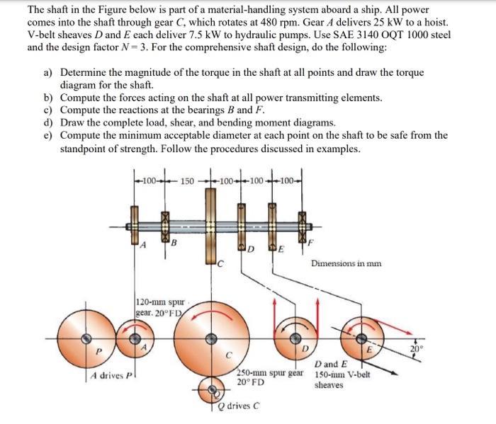
The shaft in the Figure below is part of a material-handling system aboard a ship. All power comes into the shaft through gear C,

The shaft in the Figure below is part of a material-handling system aboard a ship. All power comes into the shaft through gear C, which rotates at 480 rpm. Gear A delivers 25 kW to a hoist. V-belt sheaves D and E each deliver 7.5 kW to hydraulic pumps. Use SAE 3140 OQT 1000 steel and the design factor N= 3. For the comprehensive shaft design, do the following: a) Determine the magnitude of the torque in the shaft at all points and draw the torque diagram for the shaft. b) Compute the forces acting on the shaft at all power transmitting elements. c) Compute the reactions at the bearings B and F. d) Draw the complete load, shear, and bending moment diagrams. e) Compute the minimum acceptable diameter at each point on the shaft to be safe from the standpoint of strength. Follow the procedures discussed in examples. A drives P B 120-mm spur gear. 20FD D DE Dimensions in mm D and E 250-mm spur gear 150-im V-belt 20 FD sheaves Qdrives C
Step by Step Solution
★★★★★
3.33 Rating (147 Votes )
There are 3 Steps involved in it
Step: 1
a Determine the magnitude of the torque in the shaft at all points and draw the torque diagram for the shaft To determine the torque in the shaft at a...
Get Instant Access to Expert-Tailored Solutions
See step-by-step solutions with expert insights and AI powered tools for academic success
Step: 2

Step: 3

Ace Your Homework with AI
Get the answers you need in no time with our AI-driven, step-by-step assistance
Get Started


