Answered step by step
Verified Expert Solution
Question
1 Approved Answer
The steel girder is subject to various stresses, and in the critical area of girder the stress element is shown. Determine stress at 30
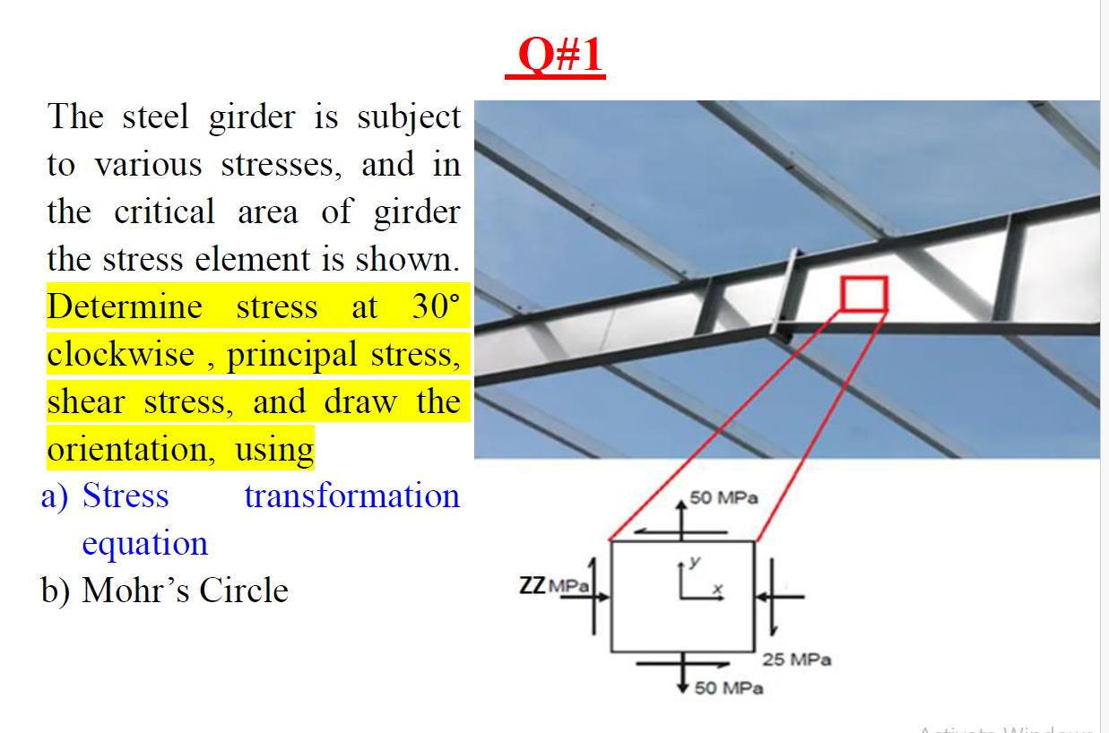
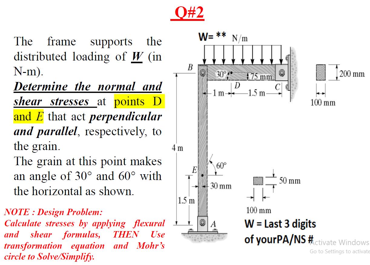
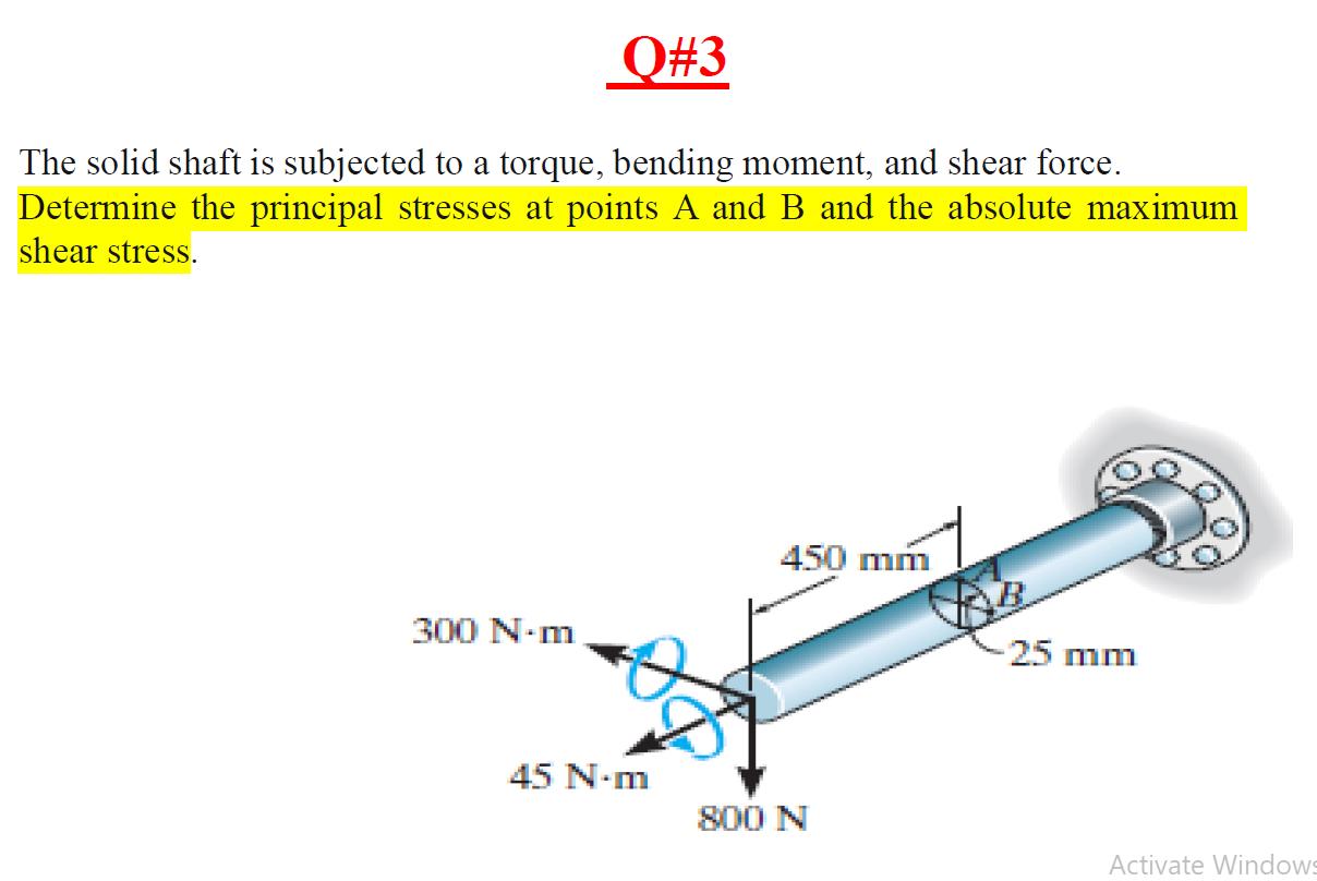
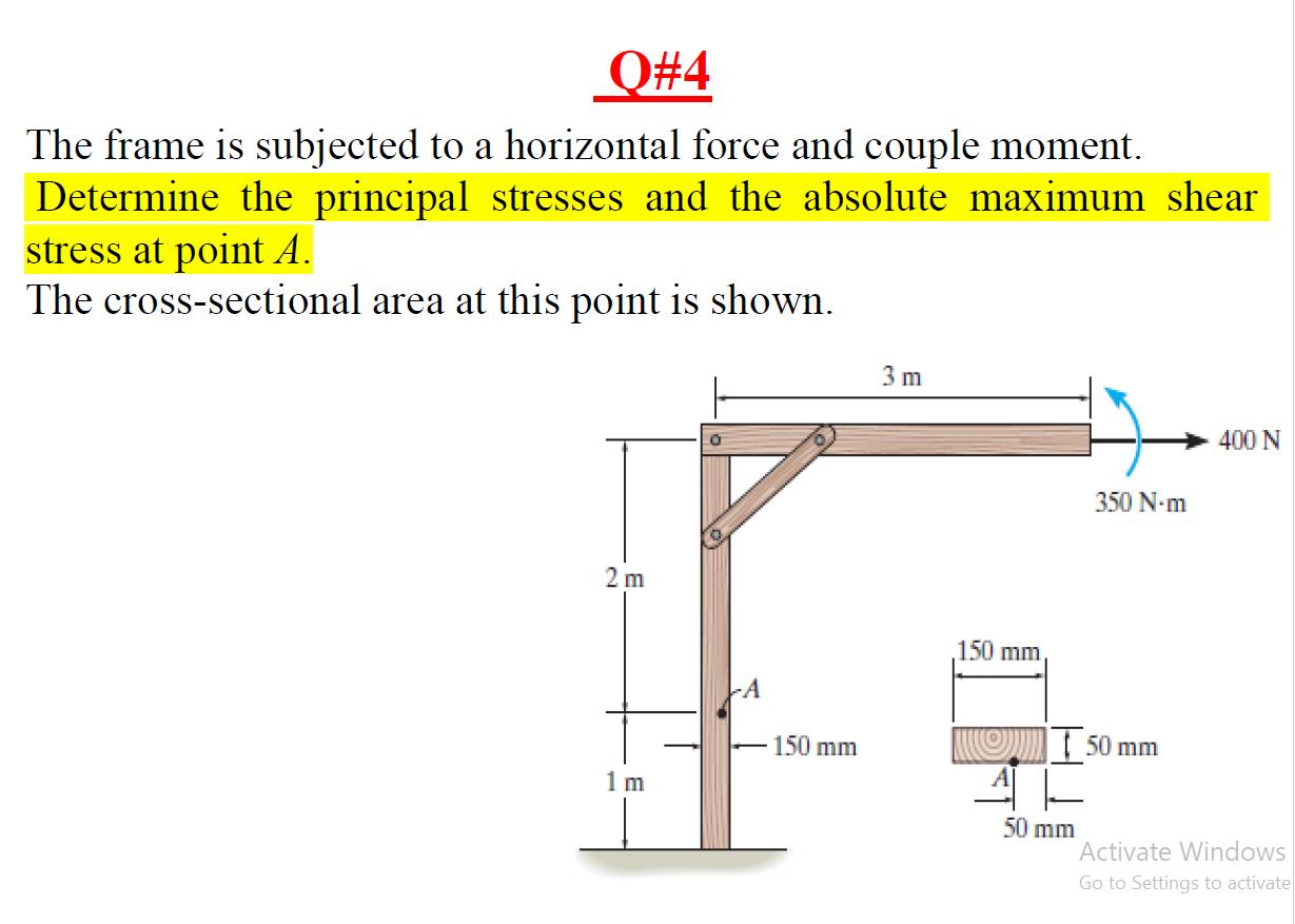
The steel girder is subject to various stresses, and in the critical area of girder the stress element is shown. Determine stress at 30 clockwise, principal stress, shear stress, and draw the orientation, using transformation Q#1 a) Stress equation b) Mohr's Circle ZZ MPa 50 MPa 50 MPa 25 MPa O#2 the W= ** N/m The frame supports distributed loading of W (in N-m). Determine the normal and shear stresses at points D and E that act perpendicular and parallel, respectively, to the grain. The grain at this point makes an angle of 30 and 60 with the horizontal as shown. NOTE: Design Problem: Calculate stresses by applying flexural and shear formulas, THEN Use transformation equation and Mohr's circle to Solve/Simplify. 4 m B 304 75 mm D 1 m -1.5 m 100 mm 60 E 30 mm 1.5 m 50 mm 200 mm 100 mm W = Last 3 digits of yourPA/NS #ctivate Windows Go to Settings to activate Q#3 The solid shaft is subjected to a torque, bending moment, and shear force. Determine the principal stresses at points A and B and the absolute maximum shear stress. 300 N-m 450 mm -25 mm 45 N-m 800 N Activate Windows Q#4 The frame is subjected to a horizontal force and couple moment. Determine the principal stresses and the absolute maximum shear stress at point A. The cross-sectional area at this point is shown. 2 m 1 m 0 150 mm 3 m 150 mm, 400 N 350 N-m 50 mm 50 mm Activate Windows Go to Settings to activate
Step by Step Solution
There are 3 Steps involved in it
Step: 1

Get Instant Access to Expert-Tailored Solutions
See step-by-step solutions with expert insights and AI powered tools for academic success
Step: 2

Step: 3

Ace Your Homework with AI
Get the answers you need in no time with our AI-driven, step-by-step assistance
Get Started


