Answered step by step
Verified Expert Solution
Question
1 Approved Answer
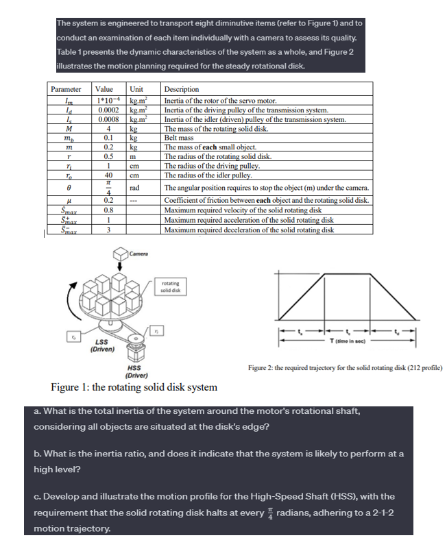
The system is engineered to transport eight diminutive items (refer to Figure 1) and to conduct an examination of each item individually with a

The system is engineered to transport eight diminutive items (refer to Figure 1) and to conduct an examination of each item individually with a camera to assess its quality. Table 1 presents the dynamic characteristics of the system as a whole, and Figure 2 illustrates the motion planning required for the steady rotational disk. Parameter Value Unit 1*10-4 kg.m 0.0002 kg.m Im la Is M mp 772 T To 0 max Sax Smax 0.0008 kg.m 4 0.1 188 0.2 0.5 1 - 40 IL 4 0.2 0.8 1 3 LSS (Driven) kg kg kg cm cm rad Camera Description Inertia of the rotor of the servo motor. Inertia of the driving pulley of the transmission system. Inertia of the idler (driven) pulley of the transmission system. The mass of the rotating solid disk. Belt mass The mass of each small object. The radius of the rotating solid disk. The radius of the driving pulley. The radius of the idler pulley. The angular position requires to stop the object (m) under the camera. Coefficient of friction between each object and the rotating solid disk. Maximum required velocity of the solid rotating disk Maximum required acceleration of the solid rotating disk Maximum required deceleration of the solid rotating disk rotating solid disk HSS (Driver) Figure 1: the rotating solid disk system T (time in sec) Figure 2: the required trajectory for the solid rotating disk (212 profile) a. What is the total inertia of the system around the motor's rotational shaft, considering all objects are situated at the disk's edge? b. What is the inertia ratio, and does it indicate that the system is likely to perform at a high level? c. Develop and illustrate the motion profile for the High-Speed Shaft (HSS), with the requirement that the solid rotating disk halts at every radians, adhering to a 2-1-2 motion trajectory.
Step by Step Solution
★★★★★
3.49 Rating (152 Votes )
There are 3 Steps involved in it
Step: 1
1 The total inertia of the system around the motors rotational shaft co...
Get Instant Access to Expert-Tailored Solutions
See step-by-step solutions with expert insights and AI powered tools for academic success
Step: 2

Step: 3

Ace Your Homework with AI
Get the answers you need in no time with our AI-driven, step-by-step assistance
Get Started


