Answered step by step
Verified Expert Solution
Question
1 Approved Answer
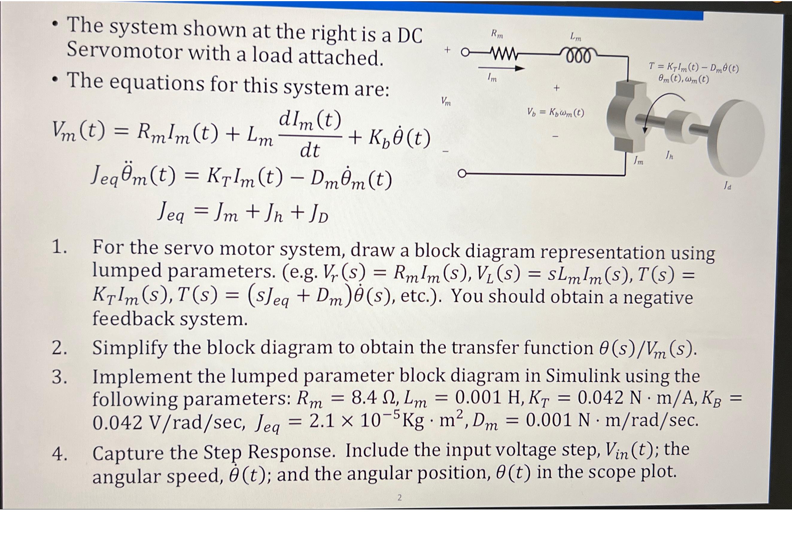
The system shown at the right is a DC Servomotor with a load attached. The equations for this system are: dlm (t) dt Jegm(t)

The system shown at the right is a DC Servomotor with a load attached. The equations for this system are: dlm (t) dt Jegm(t) = KrIm(t) DmOm (t) Jeg = Jm +Jn + JD Vm (t) = RmIm(t) + Lm 2. 3. + K (t) 4. Vm Rm ww 2 Im Lm voo Vb = Kwm (t) 1. For the servo motor system, draw a block diagram representation using lumped parameters. (e.g. Vr(s) = RmIm (S), V (s) = sLmlm (S), T(s) KrIm(s), T(s) = (sJeg + Dm)(s), etc.). You should obtain a negative feedback system. T = KrIm(t) - Dm(t) Om (t), wm (t) FO In Im Ja = Simplify the block diagram to obtain the transfer function 0(s)/Vm(s). Implement the lumped parameter block diagram in Simulink using the following parameters: Rm = 8.4 , Lm = 0.001 H, KT = 0.042 N. m/A, KB , 0.042 V/rad/sec, Jeg = 2.1 x 10⁻⁵Kg. m, Dm = 0.001 N. m/rad/sec. Capture the Step Response. Include the input voltage step, Vin (t); the angular speed, 0 (t); and the angular position, 0(t) in the scope plot.
Step by Step Solution
★★★★★
3.42 Rating (161 Votes )
There are 3 Steps involved in it
Step: 1
Part 1 Block Diagram Representation The block diagram representation of the servo motor system using ...
Get Instant Access to Expert-Tailored Solutions
See step-by-step solutions with expert insights and AI powered tools for academic success
Step: 2

Step: 3

Ace Your Homework with AI
Get the answers you need in no time with our AI-driven, step-by-step assistance
Get Started


