Answered step by step
Verified Expert Solution
Question
1 Approved Answer
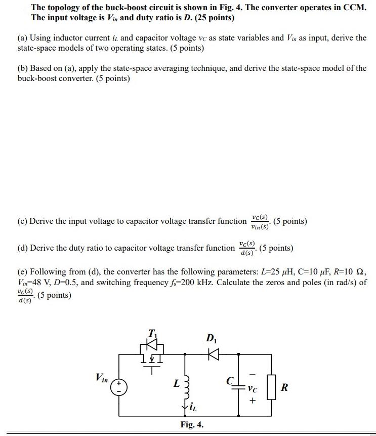
The topology of the buck-boost circuit is shown in Fig. 4. The converter operates in CCM. The input voltage is Vin and duty ratio

The topology of the buck-boost circuit is shown in Fig. 4. The converter operates in CCM. The input voltage is Vin and duty ratio is D. (25 points) (a) Using inductor current iz and capacitor voltage vc as state variables and Vin as input, derive the state-space models of two operating states. (5 points) (b) Based on (a), apply the state-space averaging technique, and derive the state-space model of the buck-boost converter. (5 points) (c) Derive the input voltage to capacitor voltage transfer function (5 points) vc(s) Vin (s) vc(s) (d) Derive the duty ratio to capacitor voltage transfer function (5 points) d(s) (e) Following from (d), the converter has the following parameters: L=25 H, C=10 F, R=10 2, Vin 48 V, D=0.5, and switching frequency fs-200 kHz. Calculate the zeros and poles (in rad/s) of vc(s) d(s) (5 points) Vin L iL Fig. 4. D 1 + VC R
Step by Step Solution
★★★★★
3.32 Rating (146 Votes )
There are 3 Steps involved in it
Step: 1
Salution 0 State states The a Switch ON During this state The inductor is conected to the input valt...
Get Instant Access to Expert-Tailored Solutions
See step-by-step solutions with expert insights and AI powered tools for academic success
Step: 2

Step: 3

Ace Your Homework with AI
Get the answers you need in no time with our AI-driven, step-by-step assistance
Get Started


