Question
The transfer functions of a long end mill attached to the spindle are measured at 2 points in both feed X and normal Y directions

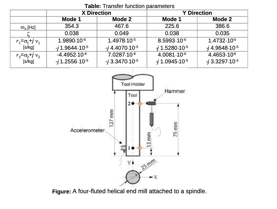
The transfer functions of a long end mill attached to the spindle are measured at 2 points in both feed X and normal Y directions (see the Figure). The accelerometer was attached to point 1, and the hammer instrumented with an impact force sensor is applied to two points. The measured transfer functions are curve fitted with modal analysis software, and the modal parameters are given in the Table. a) Identify the real modal matrix in both X and Y directions. b) Plot the mode shapes in X direction. c) Evaluate and plot the direct transfer function at point 2 in directions X and Y. (i.e. hx22, hy22=?).
n [Hz] Mode 1 354.3 0.038 Table: Transfer function parameters X Direction 1.9890-10-6 Mode 2 Mode 1 [s/kg] -j1.9644-10-5 12=0+j v [s/kg] -4.4952.10-6 -j1.2556-10-5 467.6 0.049 1.4978.10-5 -j 4.4070-10-5 7.0287.10-6 -j 3.3470.10-5 225.6 Y Direction 0.038 8.5993.10-6 j 1.5280-10-5 4.0081.10-6 -j 1.0945-10-5 Mode 2 386.6 0.035 1.4732.105 - 4.9648-10-5 4.4653.106 j 3.3297.10-5 Accelerometer 127 mm 25 mm 20 Tool Holder Hammer Tool 13 mm 75 mm Figure: A four-fluted helical end mill attached to a spindle.
Step by Step Solution
There are 3 Steps involved in it
Step: 1

Get Instant Access to Expert-Tailored Solutions
See step-by-step solutions with expert insights and AI powered tools for academic success
Step: 2

Step: 3

Ace Your Homework with AI
Get the answers you need in no time with our AI-driven, step-by-step assistance
Get Started


