Answered step by step
Verified Expert Solution
Question
1 Approved Answer
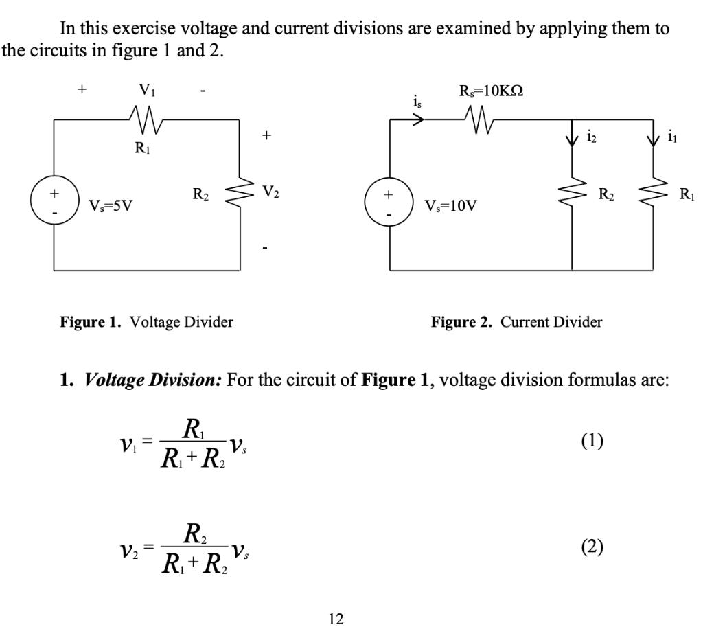
In this exercise voltage and current divisions are examined by applying them to the circuits in figure 1 and 2. V1 R=10KN is i2
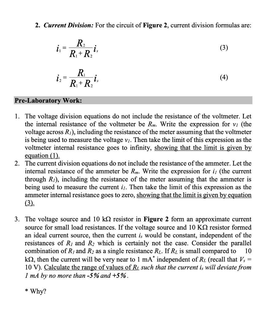
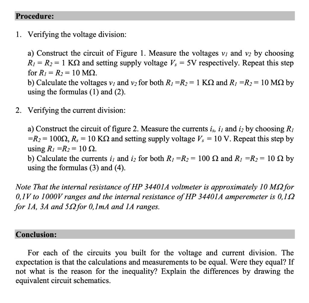
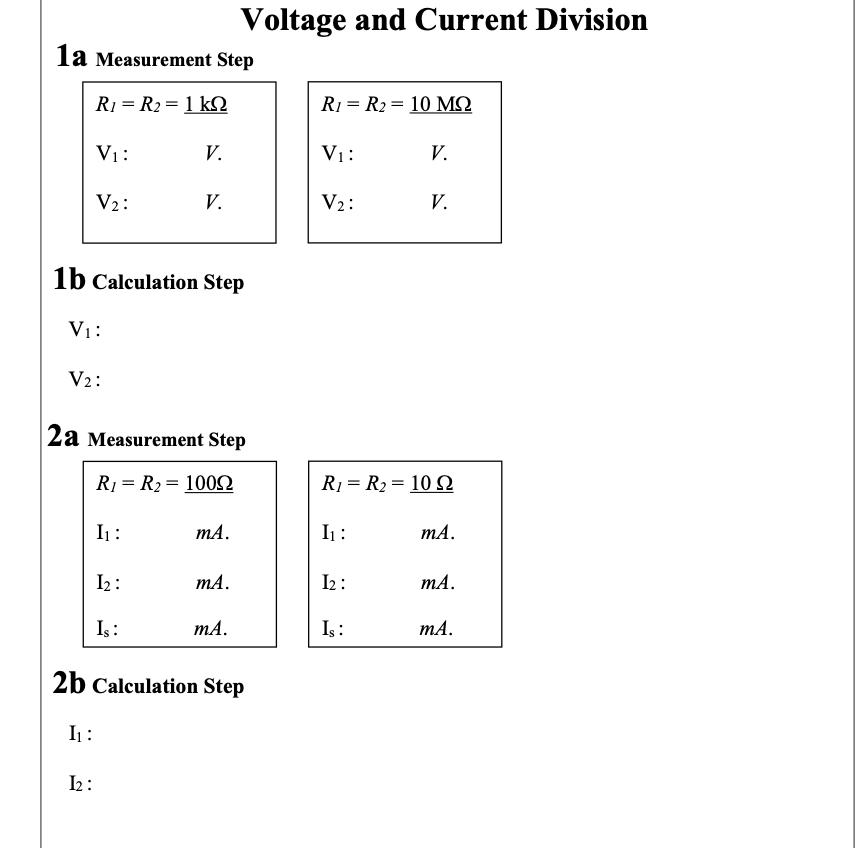
In this exercise voltage and current divisions are examined by applying them to the circuits in figure 1 and 2. V1 R=10KN is i2 R1 R2 V2 R2 R1 V=5V V,=10V Figure 1. Voltage Divider Figure 2. Current Divider 1. Voltage Division: For the circuit of Figure 1, voltage division formulas are: R R+ R: V = V. (1) R. R+ R. (2) 12 2. Current Division: For the circuit of Figure 2, current division formulas are: R. R,+R. i. i - (3) R. i. R+ R; (4) Pre-Laboratory Work: 1. The voltage division equations do not include the resistance of the voltmeter. Let the internal resistance of the voltmeter be Rm. Write the expression for vi (the voltage across RI), including the resistance of the meter assuming that the voltmeter is being used to measure the voltage v1. Then take the limit of this expression as the voltmeter internal resistance goes to infinity, showing that the limit is given by equation (1). 2. The current division equations do not include the resistance of the ammeter. Let the internal resistance of the ammeter be Rm. Write the expression for i (the current through Ri), including the resistance of the meter assuming that the ammeter is being used to measure the current i1. Then take the limit of this expression as the ammeter internal resistance goes to zero, showing that the limit is given by equation (3). 3. The voltage source and 10 k2 resistor in Figure 2 form an approximate current source for small load resistances. If the voltage source and 10 KQ resistor formed an ideal current source, then the current is would be constant, independent of the resistances of R1 and R2 which is certainly not the case. Consider the parallel combination of R1 and R2 as a single resistance RL. If RL is small compared to k2, then the current will be very near to 1 mA independent of RL (recall that Vs = 10 V). Calculate the range of values of RL such that the current is will deviate from 1 mA by no more than -5% and +5%. 10 * Why? Procedure: 1. Verifying the voltage division: a) Construct the circuit of Figure 1. Measure the voltages vi and v2 by choosing R1 = R2 = 1 KQ and setting supply voltage V, = 5V respectively. Repeat this step for R1 R2 = 10 MQ. b) Calculate the voltages vi and v2 for both R1 =R2= 1 KS2 and R1 =R2= 10 M2 by using the formulas (1) and (2). 2. Verifying the current division: a) Construct the circuit of figure 2. Measure the currents is, i and iz by choosing R1 =R2= 1002, R, = 10 K2 and setting supply voltage V, = 10 V. Repeat this step by using R1 =R2 = 10 Q. b) Calculate the currents i and iz for both R1 =R2 = 100 2 and R1 =R2 = using the formulas (3) and (4). 10 by Note That the internal resistance of HP 34401A voltmeter is approximately 10 M2 for 0,1V to 1000V ranges and the internal resistance of HP 34401A amperemeter is 0,12 for 14, 3A and 52 for 0,1mA and 1A ranges. Conclusion: For each of the circuits you built for the voltage and current division. The expectation is that the calculations and measurements to be equal. Were they equal? If not what is the reason for the inequality? Explain the differences by drawing the equivalent circuit schematics. Voltage and Current Division la Measurement Step R1 = R2 = 1 kN R1 = R2 = 10 MQ V1: V. V1: V. V2: V. V2: V. 1b Calculation Step V1: V2: 2a Measurement Step R1 = R2 = 1002 R1 = R2 = 10 SQ In : mA. I1 : mA. I2 : mA. I2 : mA. I : mA. Is: mA. 2b Calculation Step I1 : 2:
Step by Step Solution
★★★★★
3.45 Rating (155 Votes )
There are 3 Steps involved in it
Step: 1
1 a R1R21K 2a for R1R2100ohm for ...
Get Instant Access to Expert-Tailored Solutions
See step-by-step solutions with expert insights and AI powered tools for academic success
Step: 2

Step: 3

Ace Your Homework with AI
Get the answers you need in no time with our AI-driven, step-by-step assistance
Get Started


