Question: THEORY Light can be considered as a beam or ray that travels in straight lines {the law of rectilinear propagation] unless bent by reflection or
![travels in straight lines {the law of rectilinear propagation] unless bent by](https://s3.amazonaws.com/si.experts.images/answers/2024/07/6685cce1bd0f4_7696685cce19ba89.jpg)
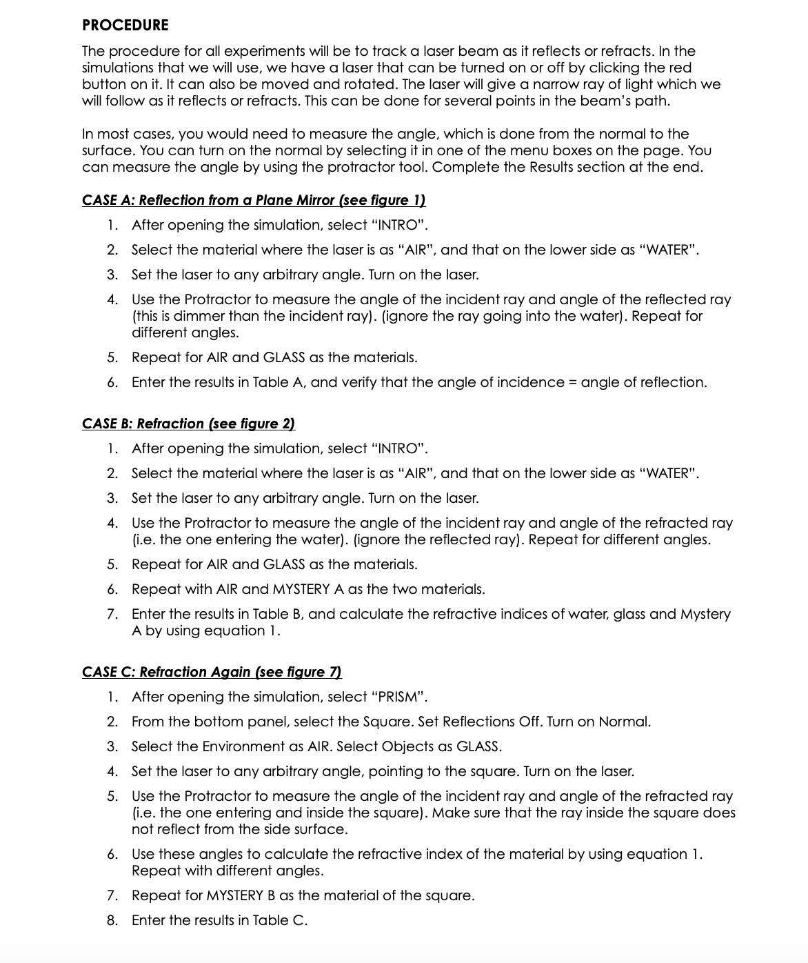
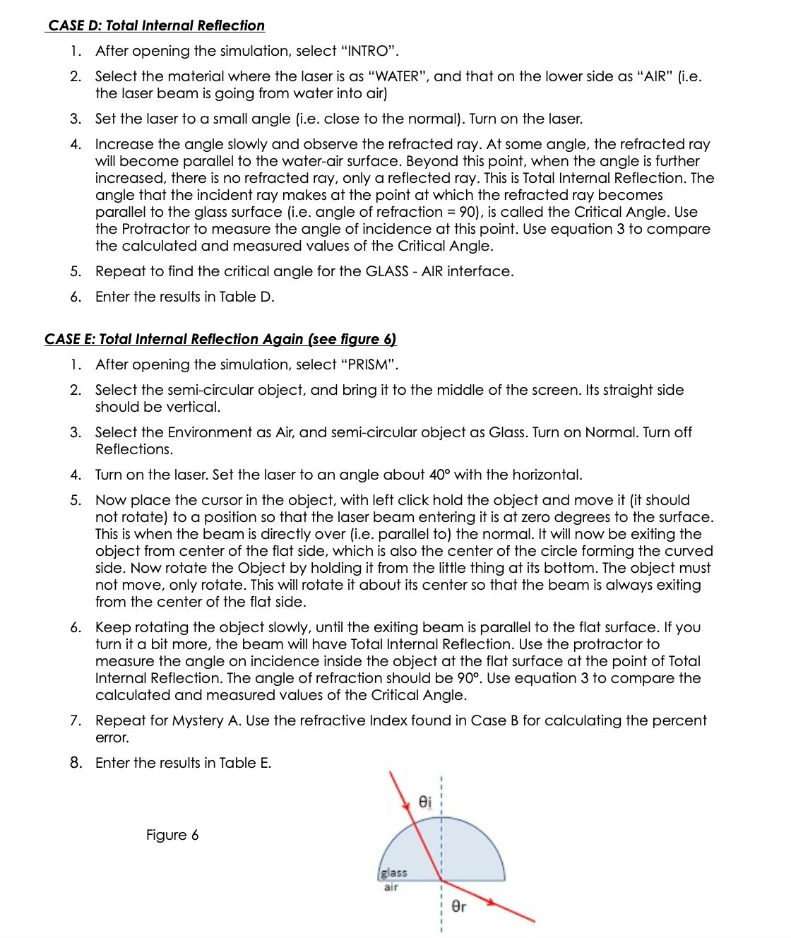
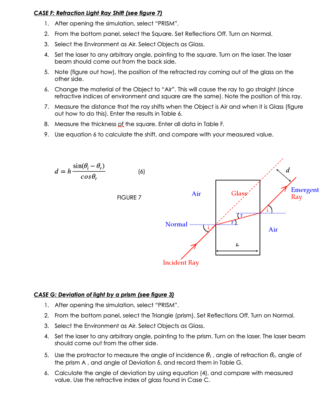
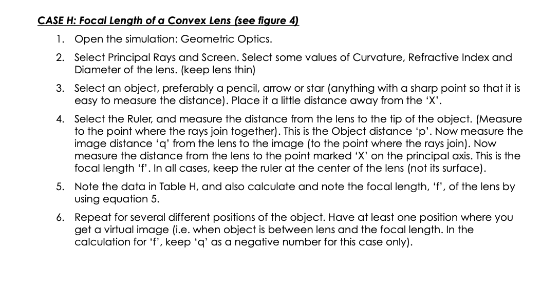
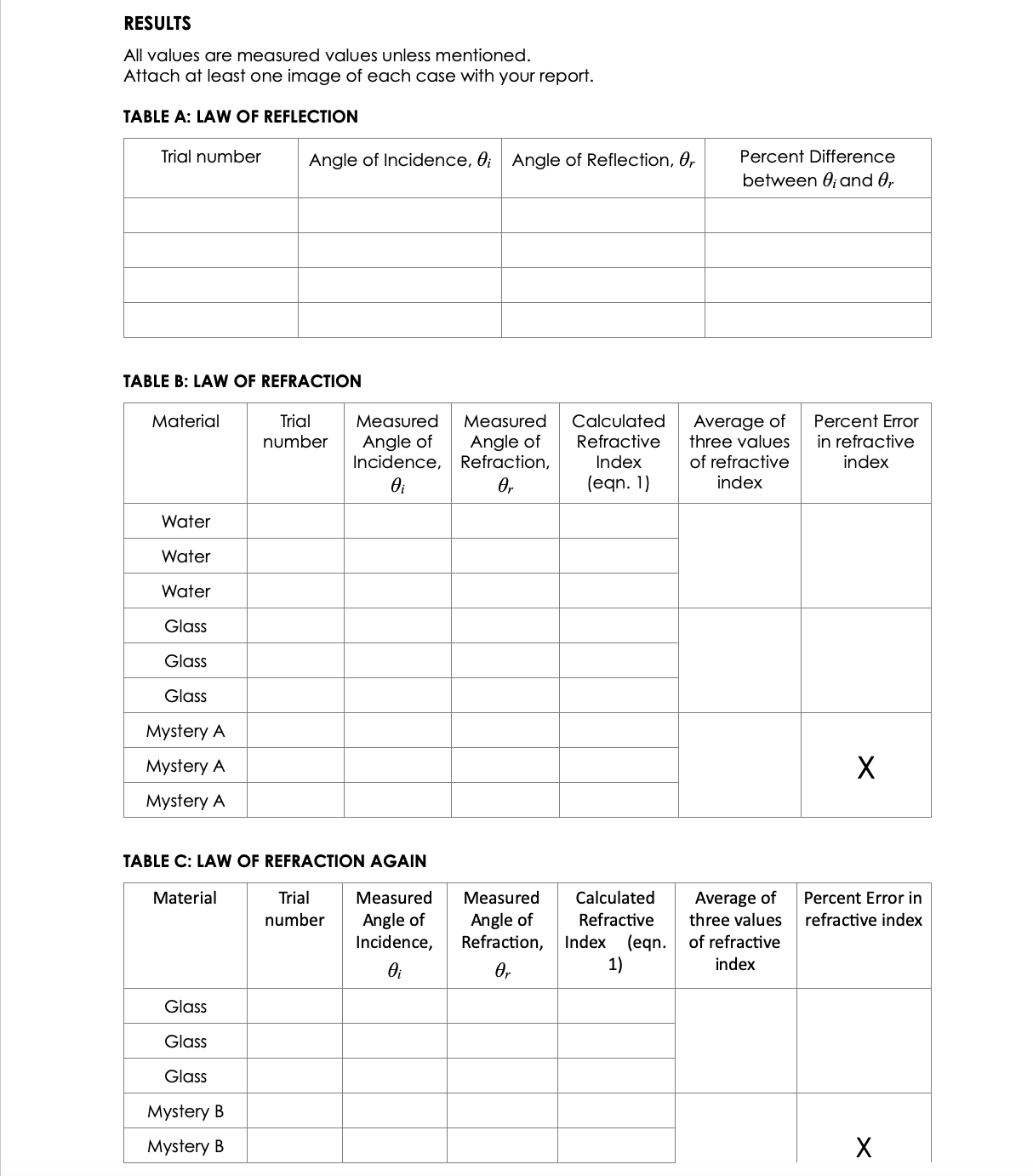
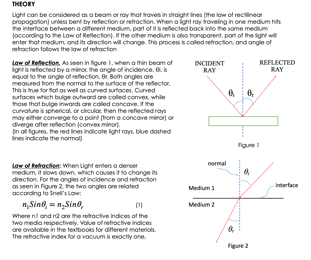
THEORY Light can be considered as a beam or ray that travels in straight lines {the law of rectilinear propagation] unless bent by reflection or refraction. When a light ray traveling in one medium hits the interface between a different medium, part of it is reflected back into the same medium {according to the Law of Reflection). If the other medium is also transparent, part of the light will enter that medium, and its direction will change. This process is called refraction, and angle of refraction follows the law of refraction low of Reflection. As seen in figure 1, when a thin beam of light is reflected by a mirror, the angle of incidence, Si, is equal to the angle of reflection, 3r. Both angles are measured from the normal to the surface of the reflector. This is true for flat as well as curved surfaces. Curved surfaces which bulge outward are called convex, while those that bulge inwards are called concave. If the curvature is spherical, or circular, then the reflected rays may either converge to a point {from a concave mirror} or diverge after reflection [convex mirror}. {In all figures, the red lines indicate light rays, blue dashed lines indicate the normal) low of Refraction: When Light enters a denser medium, it slows down. which causes it to change its direction. For the angles of incidence and refraction as seen in Figure 2, the two angles are related according to Snell's Law: nlSinSI- = nzSinHr {1) Where hi and n2 are the refractive indices of the two media respectively. Value of refractive indices are available in the textbooks for different materials. The refractive index for a vacuum is exactly one, INCIDENT REFLECTED _---o-_-_-----_-_ Figure 1 normal Medium 1 -\\ ,--- interface Medium 2 Figure 2 while for air it is 1.000 [to three places of decimal]. The speeds of light in the two media are given by: V1 \"2 V2 "1 m The change is speed is due to change in wavelength of light, and not its frequency. If the light is moving from a denser to a lighter medium, then for some angle, nlSinl may be greater than 112. In this case there is no solution for Sinz, and hence the light is not refracted, but completely reflected. This phenomenon is called total internal reflection and the angle at which this takes place is called the critical angle, given by: 6.: = sinW?) {31 l Dimension of Light. It light enters a slab of glass at one surface and leaves from another, then of the two surfaces are parallel, the ray coming out of the glass is parallel, and shifted, from the ray entering the glass [see fig. 7}. If the two surfaces are not parallel, then the ray coming out will no longer be parallel to the incoming ray. This slab now becomes a prism {see figure 3]. The angle between the original direction of the light ray, and the direction of Figure 3 the ray emergent from the prism is given by 6 as: 5=q+A m If the two surfaces are continuously curving, we obtain lenses, which can be either convex or concave {Figures 4 and 5]. The focal length of lenses depends on the curvature of the glass, as well as its refractive index. We will not be looking at Concave Lenses in this Lab. The focal Length of the convex lens can be found from: 1+1_1 {5] p q f where p is the distance to the object, a is the distance to the image and f is the distance to the focus. All distances are measured from the center of the lens. Focal Pom: Concave lens / Prnnclpal ms Fn'ncigal am Focal rang-m 5 \"my Focal Lengt h l'lGUl-(I: 4 FIGURE 5 PROCEDURE The procedure for all experimenTs will be To Track a laser beam as H reflects or refracTs. In The simulaTions ThaT we will use, we have a laser ThaT can be Turned on or off by clicking The red buTTon on H. IT can also be moved and roTaTed. The laser will give a narrow ray of lighT which we will follow as if reflecTs or refracTs. This can be done for several poinTs in The beam's paTh. In mosT cases, you would need To measure The angle, which is done from The normal To The surface. You can Turn on The normal by selecTing if in one of The menu boxes on The page. You can measure The angle by using The proTracTor Tool. CompleTe The ResulTs secTion aT The end. CASE A: Reecfion from a Plane Mirror {see figure 11 l . :l=*.'4'!\\J .01 AfTer opening The simulaTion, selecT \"INTRO". SelecT The maTerial where The laser is as "AIR". and ThaT on The lower side as "WATER\". SeT The laser To any arbiTrary angle. Turn on The laser. Use The ProTracTor To measure The angle of The incidenT ray and angle of The reflecTed ray {This is dimmer Than The incidenT ray]. [ignore The ray going info The waTer}. RepeaT for differenT angles. RepeaT for AIR and GLASS as The maTerials. EnTer The resulTs in Table A, and verify ThaT The angle of incidence = angle of reflecTion. CASE 3: Refracfion {see gure 21 l. 2 3. 4 5-" AfTer opening The simulaTion, selecT \"INTRO". SelecT The maTerial where The laser is as "AIR", and ThaT on The lower side as "WATER\". SeT The laser To any arbiTrary angle. Turn on The laser. Use The ProTracTor To measure The angle of The incidenT ray and angle of The refracTed ray {i.e. The one enTering The waTerI. (ignore The reflecTed ray). RepeaT for differenT angles. RepeaT for AIR and GLASS as The maTerials. RepeaT wiTh AIR and MYSTERY A as The Two maTerials. EnTer The resulTs in Table B, and calculaTe The refracTive indices of waTer, glass and MysTery A by using equaTion 1. CASE C: Refracfion Again (see gure 71 l. 2 3. 4. 5 AfTer opening The simulaTion, selecT \"PRISM\". From The boTTom panel, selecT The Square. SeT ReflecTions Off. Turn on Normal. SelecT The EnvironmenT as AIR. SelecT ObiecTs as GLASS. SeT The laser To any arbiTrary angle, poinTing To The square. Turn on The laser. Use The ProTracTor To measure The angle of The incidenT ray and angle of The refracTed ray {i.e. The one enTering and inside The square]. Make sure ThaT The ray inside The square does noT reflecT from The side surface. Use These angles To calculaTe The refracTive index of The maTerial by using equaTion l. RepeaT wiTh differenT angles. RepeaT for MYSTERY B as The maTerial of The square. EnTer The resulTs in Table C. CASE D: Tofaf infernal Reecfion AfTer opening The simulaTion, selecT \"INTRO". SelecT The maTerial where The laser is as "WATER", and ThaT on The lower side as \"AIR\" lie The laser beam is going from waTer inTo air} SeT The laser To a small angle [i.e. close To The normal}. Turn on The laser. Increase The angle slowly and observe The refracTed ray. AT some angle, The refracTed ray will become parallel To The waTerair surface. Beyond This poinT, when The angle is furTher increased, There is no refracTed ray, only a reflecTed ray. This is ToTal |nTerna| ReflecTion. The angle ThaT The incidenT ray makes aT The poinT aT which The refracTed ray becomes parallel To The glass surface [i.e. angle of refracTion = 90}, is called The CriTical Angle. Use The ProTracTor To measure The angle of incidence aT This poinT. Use equaTion 3 To compare The calculaTed and measured values of The CriTical Angle. RepeaT To find The criTical angle for The GLASS AIR inTerface. EnTer The resulTs in Table D. CASE E: Tofaf Infernal Reecfion Again (see figure 6! i. 2. AfTer opening The simulaTion, selecT \"PRISM\". SelecT The semicircular objecT, and bring iT To The middle of The screen. |Ts sTraighT side should be verTical. SelecT The EnvironmenT as Air, and semicircular objecT as Glass. Turn on Normal. Turn off ReflecTions. Turn on The laser. SeT The laser To an angle abouT 40 wiTh The horizonTal. Now place The cursor in The objecT, wiTh lefT click hold The objecT and move iT (iT should noT roTaTe} To a posiTion so ThaT The laser beam enTering iT is aT zero degrees To The surface. This is when The beam is direchy over [i.e. parallel To) The normal. |T will now be exiTing The objecT from cenTer of The flaT side, which is also The cenTer of The circle forming The curved side. Now roTaTe The ObiecT by holding H from The liTTle Thing aT iTs boTTom. The objecT musT noT move, only roTaTe. This will roTaTe iT abouT iTs cenTer so ThaT The beam is always exiTing from The cenTer of The flaT side. Keep roTaTing The objecT slowly, unTil The exiTing beam is parallel To The flaT surface. If you Turn iT a biT more, The beam will have ToTal InTernal ReflecTion. Use The proTracTor To measure The angle on incidence inside The objecT aT The flaT surface aT The poinT of ToTal InTernal ReflecTion. The angle of refracTion should be 90. Use equaTion 3 To compare The calculaTed and measured values of The CriTical Angle. RepeaT for MysTery A. Use The refracTive Index found in Case B for calculaTing The percenT error. EnTer The resulTs in Table E. Figure 6 CASE F: Refraction Light Ray Shift (see figure 7) 1. After opening the simulation, select "PRISM". 2. From the bottom panel, select the Square. Set Reflections Off. Turn on Normal. 3. Select the Environment as Air. Select Objects as Glass. 4. Set the laser to any arbitrary angle, pointing to the square. Turn on the laser. The laser beam should come out from the back side. 5. Note (figure out how), the position of the refracted ray coming out of the glass on the other side. 6. Change the material of the Object to "Air". This will cause the ray to go straight (since refractive indices of environment and square are the same). Note the position of this ray. Measure the distance that the ray shifts when the Object is Air and when it is Glass (figure out how to do this). Enter the results in Table 6. 8. Measure the thickness of the square. Enter all data in Table F. 9. Use equation 6 to calculate the shift, and compare with your measured value. sin(0; - 0,) d = h- (6) cost, Glass' Emergent FIGURE 7 Air Ray Normal ..... Air Incident Ray CASE G: Deviation of light by a prism (see figure 3) 1. After opening the simulation, select "PRISM". 2. From the bottom panel, select the Triangle (prism). Set Reflections Off. Turn on Normal. 3. Select the Environment as Air. Select Objects as Glass. 4. Set the laser to any arbitrary angle, pointing to the prism. Turn on the laser. The laser beam should come out from the other side. 5. Use the protractor to measure the angle of incidence ; , angle of refraction Or, angle of the prism A , and angle of Deviation 8, and record them in Table G. 6. Calculate the angle of deviation by using equation (4), and compare with measured value. Use the refractive index of glass found in Case C.CASE H: Focal Length of a Convex Lens (see gure 41 l. 2. Open the simulation: Geometric Optics. Select Principal Rays and Screen. Select some values of Curvature, Refractive Index and Diameter of the lens. {keep lens thin) Select an object, preferably a pencil. arrow or star [anything with a sharp point so that it is easy to measure the distance). Place it a little distance away from the 'X'. Select the Ruler, and measure the distance from the lens to the tip of the object. [Measure to the point where the rays join together}. This is the Object distance 'p'. Now measure the image distance 'q' from the lens to the image {to the point where the rays join}. Now measure the distance from the lens to the point marked 'X' on the principal axis. This is the focal length 'f'. In all cases. keep the ruler at the center of the lens {not its surface}. Note the data in Table H, and also calculate and note the focal length. 'f'. of the lens by using equation 5. Repeat for several different positions of the object. Have at least one position where you get a virtual image lie. when object is between lens and the focal length. In the calculation for 'f'. keep 'q' as a negative number for this case only). RESULTS All values are measured values unless mentioned. Attach at least one image of each case with your report. TABLE A: LAW OF REFLECTION Trial number Angle of Incidence, 3;- Angle of Reflection, 6r Percent Difference between Stand 6, TABLE B: LAW OF REFRACTION Material Trial Measured Measured Calculated Average of Percent Error number Angle of Angle of Refractive three values in refractive Incidence, Refraction, Index of refractive index .9;- l9, lean. 1} index Water Water Water Glass Glass Glass Mystery A Mystery A X Mystery A TABLE C: LAW OF REFRACTION AGAIN Material Trial Measured Measured Calculated Average of Percent Error in number Angle of Angle of Refractive three values refractive index Incidence, Refraction, Index (eqn. of refractive 9f 0r 1} index Glass Glass Glass Mystery B Mystery B X
Step by Step Solution
There are 3 Steps involved in it

Get step-by-step solutions from verified subject matter experts


