Question
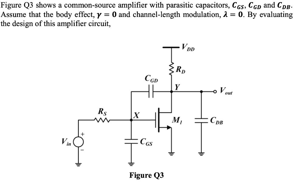
Figure Q3 shows a common-source amplifier with parasitic capacitors, CGS, CGD and CDB. Assume that the body effect, y = 0 and channel-length modulation,


Figure Q3 shows a common-source amplifier with parasitic capacitors, CGS, CGD and CDB. Assume that the body effect, y = 0 and channel-length modulation, = 0. By evaluating the design of this amplifier circuit, Vin Rs CGD HH CGS Figure Q3 V DD By using Miller's Theorem, deduce the expression for the total input and output capacitances seen at node X and node Y, respectively. By using open-circuit time constant method, deduce: i) the expression of the input pole frequency, @in, at node X. ii) the expression of the output pole frequency, @out, at node Y.
Step by Step Solution
3.32 Rating (176 Votes )
There are 3 Steps involved in it
Step: 1
i ii The input pole frequency and output pole frequency Ive know that ac equivalent n ...
Get Instant Access to Expert-Tailored Solutions
See step-by-step solutions with expert insights and AI powered tools for academic success
Step: 2

Step: 3

Ace Your Homework with AI
Get the answers you need in no time with our AI-driven, step-by-step assistance
Get StartedRecommended Textbook for
Ethical Obligations and Decision Making in Accounting Text and Cases
Authors: Steven Mintz, Roselyn Morris
4th edition
978-1259543470, 1259543471, 978-1259730191
Students also viewed these Accounting questions
Question
Answered: 1 week ago
Question
Answered: 1 week ago
Question
Answered: 1 week ago
Question
Answered: 1 week ago
Question
Answered: 1 week ago
Question
Answered: 1 week ago
Question
Answered: 1 week ago
Question
Answered: 1 week ago
Question
Answered: 1 week ago
Question
Answered: 1 week ago
Question
Answered: 1 week ago
Question
Answered: 1 week ago
Question
Answered: 1 week ago
Question
Answered: 1 week ago
Question
Answered: 1 week ago
Question
Answered: 1 week ago
Question
Answered: 1 week ago
Question
Answered: 1 week ago
Question
Answered: 1 week ago
Question
Answered: 1 week ago
Question
Answered: 1 week ago
Question
Answered: 1 week ago
View Answer in SolutionInn App


