Question
This is a project about converting AC to DC supply. We do not have access to a transformer so we got to work without that(Please


This is a project about converting AC to DC supply. We do not have access to a transformer so we got to work without that(Please include the necessary calculations for the input supply(Transformer output)). Additionally, we only have 3 diodes to work with so we cannot build a 4 diode bridge rectifier(Maybe a 2 diode rectifier with capacitors and resistors?). Using all the information I provided please help me design a circuit and suggest values for each component used. Please also help answer the questions asked as well. I would really appreciate it. If you have any questions ask away in the comments
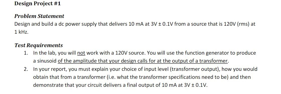
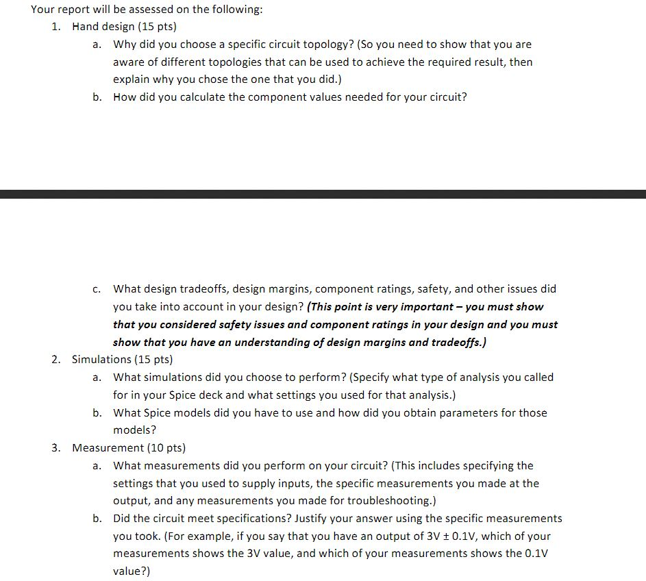
Design Project #1 Problem Statement Design and build a dc power supply that delivers 10 mA at 3V + 0.1V from a source that is 120V (rms) at 1 kHz. Test Requirements 1. In the lab, you will not work with a 120V source. You will use the function generator to produce a sinusoid of the amplitude that your design calls for at the output of a transformer. 2. In your report, you must explain your choice of input level (transformer output), how you would obtain that from a transformer (i.e. what the transformer specifications need to be) and then demonstrate that your circuit delivers a final output of 10 mA at 3V + 0.1v. 1. Carefully simulate your circuit before you attempt to build it. 2. Make sure that you are aware of the current, voltage, and power ratings for various components and do not exceed them. 3. Make sure that if you use a polarized capacitor that you connect it with the correct polarity. Report Requirements Your submitted report should not exceed four pages. You are allowed: 1. A maximum of 2 pages showing your hand analysis and discussing design considerations; 2. A maximum of 1 page showing figures (circuit diagram, simulation results, etc.); and 3. A maximum of 1 page describing your simulations, reporting measured results, and comparing theory with experiment. Your report will be assessed on the following: 1. Hand design (15 pts) a. Why did you choose a specific circuit topology? (so you need to show that you are aware of different topologies that can be used to achieve the required result, then explain why you chose the one that you did.) b. How did you calculate the component values needed for your circuit? c. What design tradeoffs, design margins, component ratings, safety, and other issues did you take into account in your design? (This point is very important - you must show that you considered safety issues and component ratings in your design and you must show that you have an understanding of design margins and tradeoffs.) 2. Simulations (15 pts) a. What simulations did you choose to perform? (Specify what type of analysis you called for in your Spice deck and what settings you used for that analysis.) b. What Spice models did you have to use and how did you obtain parameters for those models? 3. Measurement (10 pts) a. What measurements did you perform on your circuit? (This includes specifying the settings that you used to supply inputs, the specific measurements you made at the output, and any measurements you made for troubleshooting.) b. Did the circuit meet specifications? Justify your answer using the specific measurements you took. (For example, if you say that you have an output of 3V + 0.1V, which of your measurements shows the 3V value, and which of your measurements shows the 0.1V value?) Design Project #1 Problem Statement Design and build a dc power supply that delivers 10 mA at 3V + 0.1V from a source that is 120V (rms) at 1 kHz. Test Requirements 1. In the lab, you will not work with a 120V source. You will use the function generator to produce a sinusoid of the amplitude that your design calls for at the output of a transformer. 2. In your report, you must explain your choice of input level (transformer output), how you would obtain that from a transformer (i.e. what the transformer specifications need to be) and then demonstrate that your circuit delivers a final output of 10 mA at 3V + 0.1v. 1. Carefully simulate your circuit before you attempt to build it. 2. Make sure that you are aware of the current, voltage, and power ratings for various components and do not exceed them. 3. Make sure that if you use a polarized capacitor that you connect it with the correct polarity. Report Requirements Your submitted report should not exceed four pages. You are allowed: 1. A maximum of 2 pages showing your hand analysis and discussing design considerations; 2. A maximum of 1 page showing figures (circuit diagram, simulation results, etc.); and 3. A maximum of 1 page describing your simulations, reporting measured results, and comparing theory with experiment. Your report will be assessed on the following: 1. Hand design (15 pts) a. Why did you choose a specific circuit topology? (so you need to show that you are aware of different topologies that can be used to achieve the required result, then explain why you chose the one that you did.) b. How did you calculate the component values needed for your circuit? c. What design tradeoffs, design margins, component ratings, safety, and other issues did you take into account in your design? (This point is very important - you must show that you considered safety issues and component ratings in your design and you must show that you have an understanding of design margins and tradeoffs.) 2. Simulations (15 pts) a. What simulations did you choose to perform? (Specify what type of analysis you called for in your Spice deck and what settings you used for that analysis.) b. What Spice models did you have to use and how did you obtain parameters for those models? 3. Measurement (10 pts) a. What measurements did you perform on your circuit? (This includes specifying the settings that you used to supply inputs, the specific measurements you made at the output, and any measurements you made for troubleshooting.) b. Did the circuit meet specifications? Justify your answer using the specific measurements you took. (For example, if you say that you have an output of 3V + 0.1V, which of your measurements shows the 3V value, and which of your measurements shows the 0.1V value?)Step by Step Solution
There are 3 Steps involved in it
Step: 1

Get Instant Access to Expert-Tailored Solutions
See step-by-step solutions with expert insights and AI powered tools for academic success
Step: 2

Step: 3

Ace Your Homework with AI
Get the answers you need in no time with our AI-driven, step-by-step assistance
Get Started


