

Question: This is aproject for digital logic can you please solve Part F and Part G this a Digital logic mini project A. Objectives The objectives
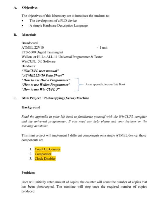
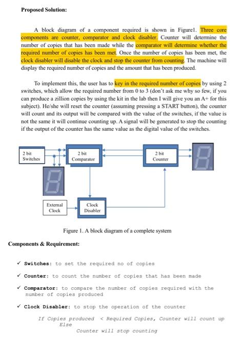
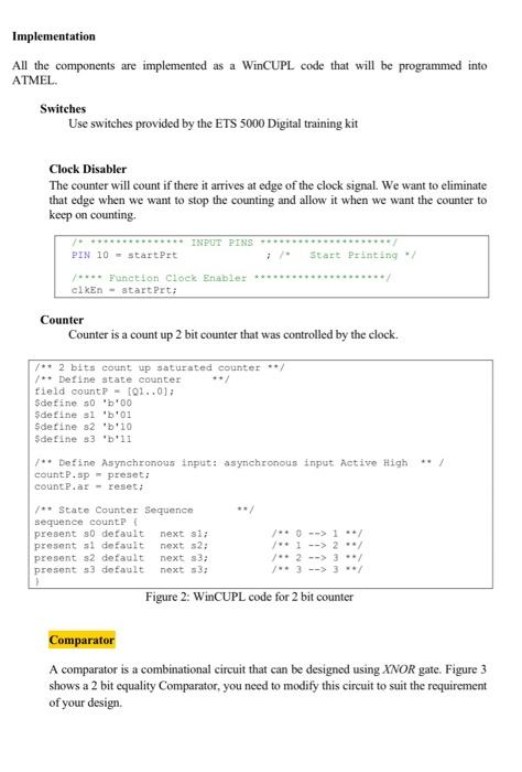
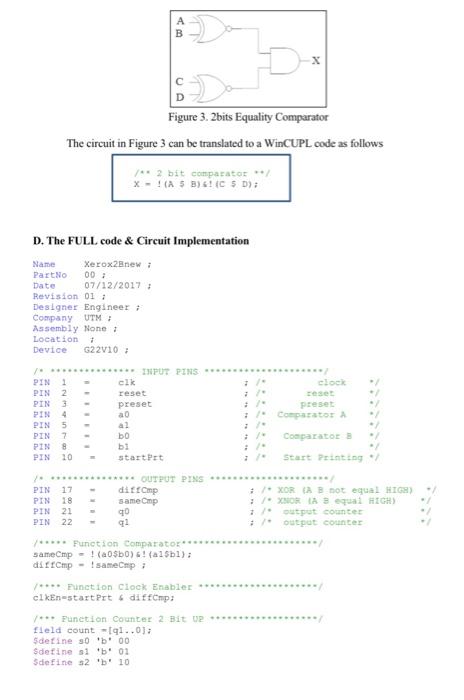
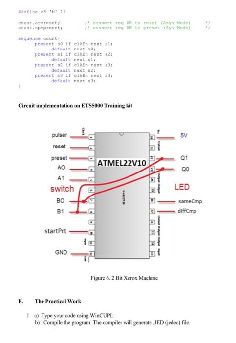
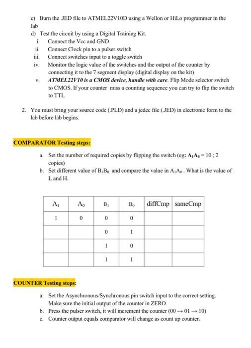
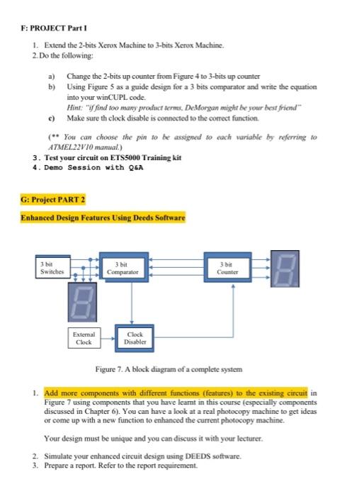
A. Objectives The objectives of this laboratory are to introduce the students to The development of a PLD device A simple Hardware Description Language B. Materials Breadboard ATMEL 22V10 - 1 unit ETS-5000 Digital Training kit Wellon or Hi-Lo ALL-11 Universal Programmer & Tester WinCUPL 5.0 Software Handouts: "WinCUPL user manual "ATMEL22V10 Data Sheer" "How to use Hi-Lo Programmer" "How to use Wellon Programmer" As an appendix in your Lab Book "How to use Win CUPL 5" C. Mini Project : Photocopying (Xerox) Machine Background Read the appendix in your lab book to familiarize yourself with the WinCUPL compiler and the universal programmer. If you need any help please ask your lecturer or the teaching assistants This mini project will implement 3 different components on a single ATMEL device, those components are 1. Count Up Counter 2. Comparator 3. Clock Disabler Problem: User will initially enter amount of copies, the counter will count the number of copies that has been photocopied. The machine will stop once the required number of copies produced Proposed Solution: A block diagram of a component required is shown in Figurel. Three core components are counter, comparator and clock disabler. Counter will determine the number of copies that has been made while the comparator will determine whether the required number of copies has been met. Once the number of copies has been met, the clock disabler will disable the clock and stop the counter from counting. The machine will display the required number of copies and the amount that has been produced. To implement this, the user has to key in the required number of copies by using 2 switches, which allow the required number from 0 to 3 (don't ask me why so few, if you can produce a zillion copies by using the kit in the lab then I will give you an A+ for this subject). He/she will reset the counter (assuming pressing a START button), the counter will count and its output will be compared with the value of the switches, if the value is not the same it will continue counting up. A signal will be generated to stop the counting if the output of the counter has the same value as the digital value of the switches. 2 bit Switches 2 bit Comparator 2 bit Counter External Clock Clock Disabler Figure 1. A block diagram of a complete system Components & Requirement: Switches: to set the required no ot copies Counter: to count the number of copies that has been made Comparator: to compare the number of copies required with the number of copies produced Clock Disabler: to stop the operation of the counter IF Copies produced 2 **/ present s2 default next 83; 2 --> 3 / present 33 default next 53: Figure 2: WinCUPL code for 2 bit counter Comparator A comparator is a combinational circuit that can be designed using XNOR gate. Figure 3 shows a 2 bit equality Comparator, you need to modify this circuit to suit the requirement of your design A B X Figure 3.2bits Equality Comparator The circuit in Figure 3 can be translated to a WinCUPL code as follows /** 2 bit comparator / X - A 5 5) 6C $ ); 00 D. The FULL code & Circuit Implementation Name Xerox2new : Part No Date 07/12/2017 Revision 01 ; Designer Engineer; Company UTM : Assembly None ? Location 7 Device G22110 clock * INPUT PINS clk reset preset ao PIN 1 PIN 2 PIN 3 PIN 4 PIN 5 PIN 7 PIN 8 PIN 10 preset Comparator A Comparator bo bi startet Start Printing PIN PIN PIN PIN 17 18 21 22 ***** OUTPUT PINS dicamp samemp 90 ; /XOR A B not equal HIGH) / XBOR A 3 equal HIGH output counter output counter /***** Function Comparator SameCmp - ! (OSO)! (albl); dar Cmp - I sameCmp; *** Function Clock Enable *** clkEn-start Prt 6 ditempi *** Function Counter 2 Bit U. field count -91..0); Sdetine 50 'b00 Sdetine 1 b 01 Sdefine 32 b' 10 Sdefine a3 11 count.ar reset count.sp preset: /conneet reg AR to reset syn Mode) connect reg AR to preset (Syn Mode sequence count! present 50 if elken next sli default next 30; present slit elken next 52 detault next sli present 52 18 elken next 33; default next 32; present 3 if elkEn next 53: default next 337 Circuit implementation on ETS5000 Training kit 5V puiser reset preset s1 ATMEL22V10 AO Q0 A1 switch DODODOVODOC LED GALIN = sameCmp diffCmp B1 startPrt 1 GND Figure 6.2 Bit Xerox Machine E. The Practical Work 1. a) Type your code using WinCUPL. b) Compile the program. The compiler will generate JED Jedec) file. c) Burn the JED file to ATMEL22V10D using a Wellon or Hilo programmer in the lab d) Test the circuit by using a Digital Training Kit. i Connect the Vee and GND ii. Connect Clock pin to a pulser switch iii. Connect switches input to a toggle switch iv. Monitor the logic value of the switches and the output of the counter by connecting it to the 7 segment display (digital display on the kit) v. ATMEL22V10 is a CMOS device, handle with care. Flip Mode selector switch to CMOS. If your counter miss a counting sequence you can try to flip the switch to TTL 2. You must bring your source code (PLD) and a jedec file (JED) in electronic form to the lab before lab begins. COMPARATOR Testing steps: a Set the number of required copies by flipping the switch (eg: A,A- 10:2 copies) b. Set different value of B, B, and compare the value in A, A. What is the value of L and H. A A. BI diffCmp sameCmp 1 0 0 0 0 1 1 0 1 1 COUNTER Testing steps: a. Set the Asynchronous/Synchronous pin switch input to the correct setting, Make sure the initial output of the counter in ZERO. b. Press the pulser switch, it will increment the counter (00-01-10) c. Counter output equals comparator will change as count up counter. F: PROJECT Part 1 1. Extend the 2-bits Xerox Machine to 3-bits Xerox Machine. 2. Do the following: a) Change the 2-bits up counter from Figure 4 to 3-bits up counter b) Using Figure 5 as a guide design for a 3 bits comparator and write the equation into your winCUPL code Hint: "V find too many product terms, De Morgan might be your best friend c) Make sure th clock disable is connected to the correct function. (** You can choose the pain to be assigned to each wariable by referring to ATMEL22V10 manual.) 3. Test your circuit on ETS5000 Training kit 4. Demo Session with Q&A G: Project PART 2 Enhanced Design Features Using Deeds Software 3 bit Switches 3 bit Comparator Counter External Clock Clock Disabler Figure 7. A block diagram of a complete system 1. Add more components with different functions (fcatures) to the existing circuit in Figure 7 using components that you have learnt in this course (especially components discussed in Chapter 6). You can have a look at a real photocopy machine to get ideas or come up with a new function to enhanced the current photocopy machine Your design must be unique and you can discuss it with your lecturer. 2. Simulate your enhanced circuit design using DEEDS software. 3. Prepare a report. Refer to the report requirement. A. Objectives The objectives of this laboratory are to introduce the students to The development of a PLD device A simple Hardware Description Language B. Materials Breadboard ATMEL 22V10 - 1 unit ETS-5000 Digital Training kit Wellon or Hi-Lo ALL-11 Universal Programmer & Tester WinCUPL 5.0 Software Handouts: "WinCUPL user manual "ATMEL22V10 Data Sheer" "How to use Hi-Lo Programmer" "How to use Wellon Programmer" As an appendix in your Lab Book "How to use Win CUPL 5" C. Mini Project : Photocopying (Xerox) Machine Background Read the appendix in your lab book to familiarize yourself with the WinCUPL compiler and the universal programmer. If you need any help please ask your lecturer or the teaching assistants This mini project will implement 3 different components on a single ATMEL device, those components are 1. Count Up Counter 2. Comparator 3. Clock Disabler Problem: User will initially enter amount of copies, the counter will count the number of copies that has been photocopied. The machine will stop once the required number of copies produced Proposed Solution: A block diagram of a component required is shown in Figurel. Three core components are counter, comparator and clock disabler. Counter will determine the number of copies that has been made while the comparator will determine whether the required number of copies has been met. Once the number of copies has been met, the clock disabler will disable the clock and stop the counter from counting. The machine will display the required number of copies and the amount that has been produced. To implement this, the user has to key in the required number of copies by using 2 switches, which allow the required number from 0 to 3 (don't ask me why so few, if you can produce a zillion copies by using the kit in the lab then I will give you an A+ for this subject). He/she will reset the counter (assuming pressing a START button), the counter will count and its output will be compared with the value of the switches, if the value is not the same it will continue counting up. A signal will be generated to stop the counting if the output of the counter has the same value as the digital value of the switches. 2 bit Switches 2 bit Comparator 2 bit Counter External Clock Clock Disabler Figure 1. A block diagram of a complete system Components & Requirement: Switches: to set the required no ot copies Counter: to count the number of copies that has been made Comparator: to compare the number of copies required with the number of copies produced Clock Disabler: to stop the operation of the counter IF Copies produced 2 **/ present s2 default next 83; 2 --> 3 / present 33 default next 53: Figure 2: WinCUPL code for 2 bit counter Comparator A comparator is a combinational circuit that can be designed using XNOR gate. Figure 3 shows a 2 bit equality Comparator, you need to modify this circuit to suit the requirement of your design A B X Figure 3.2bits Equality Comparator The circuit in Figure 3 can be translated to a WinCUPL code as follows /** 2 bit comparator / X - A 5 5) 6C $ ); 00 D. The FULL code & Circuit Implementation Name Xerox2new : Part No Date 07/12/2017 Revision 01 ; Designer Engineer; Company UTM : Assembly None ? Location 7 Device G22110 clock * INPUT PINS clk reset preset ao PIN 1 PIN 2 PIN 3 PIN 4 PIN 5 PIN 7 PIN 8 PIN 10 preset Comparator A Comparator bo bi startet Start Printing PIN PIN PIN PIN 17 18 21 22 ***** OUTPUT PINS dicamp samemp 90 ; /XOR A B not equal HIGH) / XBOR A 3 equal HIGH output counter output counter /***** Function Comparator SameCmp - ! (OSO)! (albl); dar Cmp - I sameCmp; *** Function Clock Enable *** clkEn-start Prt 6 ditempi *** Function Counter 2 Bit U. field count -91..0); Sdetine 50 'b00 Sdetine 1 b 01 Sdefine 32 b' 10 Sdefine a3 11 count.ar reset count.sp preset: /conneet reg AR to reset syn Mode) connect reg AR to preset (Syn Mode sequence count! present 50 if elken next sli default next 30; present slit elken next 52 detault next sli present 52 18 elken next 33; default next 32; present 3 if elkEn next 53: default next 337 Circuit implementation on ETS5000 Training kit 5V puiser reset preset s1 ATMEL22V10 AO Q0 A1 switch DODODOVODOC LED GALIN = sameCmp diffCmp B1 startPrt 1 GND Figure 6.2 Bit Xerox Machine E. The Practical Work 1. a) Type your code using WinCUPL. b) Compile the program. The compiler will generate JED Jedec) file. c) Burn the JED file to ATMEL22V10D using a Wellon or Hilo programmer in the lab d) Test the circuit by using a Digital Training Kit. i Connect the Vee and GND ii. Connect Clock pin to a pulser switch iii. Connect switches input to a toggle switch iv. Monitor the logic value of the switches and the output of the counter by connecting it to the 7 segment display (digital display on the kit) v. ATMEL22V10 is a CMOS device, handle with care. Flip Mode selector switch to CMOS. If your counter miss a counting sequence you can try to flip the switch to TTL 2. You must bring your source code (PLD) and a jedec file (JED) in electronic form to the lab before lab begins. COMPARATOR Testing steps: a Set the number of required copies by flipping the switch (eg: A,A- 10:2 copies) b. Set different value of B, B, and compare the value in A, A. What is the value of L and H. A A. BI diffCmp sameCmp 1 0 0 0 0 1 1 0 1 1 COUNTER Testing steps: a. Set the Asynchronous/Synchronous pin switch input to the correct setting, Make sure the initial output of the counter in ZERO. b. Press the pulser switch, it will increment the counter (00-01-10) c. Counter output equals comparator will change as count up counter. F: PROJECT Part 1 1. Extend the 2-bits Xerox Machine to 3-bits Xerox Machine. 2. Do the following: a) Change the 2-bits up counter from Figure 4 to 3-bits up counter b) Using Figure 5 as a guide design for a 3 bits comparator and write the equation into your winCUPL code Hint: "V find too many product terms, De Morgan might be your best friend c) Make sure th clock disable is connected to the correct function. (** You can choose the pain to be assigned to each wariable by referring to ATMEL22V10 manual.) 3. Test your circuit on ETS5000 Training kit 4. Demo Session with Q&A G: Project PART 2 Enhanced Design Features Using Deeds Software 3 bit Switches 3 bit Comparator Counter External Clock Clock Disabler Figure 7. A block diagram of a complete system 1. Add more components with different functions (fcatures) to the existing circuit in Figure 7 using components that you have learnt in this course (especially components discussed in Chapter 6). You can have a look at a real photocopy machine to get ideas or come up with a new function to enhanced the current photocopy machine Your design must be unique and you can discuss it with your lecturer. 2. Simulate your enhanced circuit design using DEEDS software. 3. Prepare a report. Refer to the report requirement
Step by Step Solution
There are 3 Steps involved in it

Get step-by-step solutions from verified subject matter experts